Unlike biological systems, which can use muscles, robots that try to imitate them don’t have particularly fast, powerful, compact linear actuators available. This puts walking robots at a particular disadvantage, since they can’t spread their actuators along a limb and have to place them right at the joint. [Food for Robots] took on the challenge of building such a joint-mounted actuator, and shared the results in a recent video.
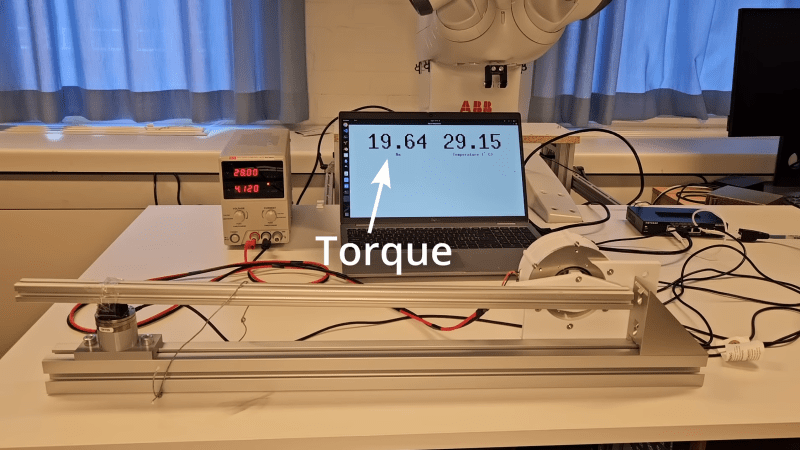
[Food for Robots] is building a walking robot, so he needed a compact, lightweight, and backdrivable actuator capable of producing 20 Newton-meters of torque. He’d previously built a largely 3D-printed actuator, but when he tried to exceed 10 Nm of torque with it, various parts kept breaking. He therefore machined the second iteration out of aluminum; since it didn’t need to be 3D printed, he switched from a Capstan drive to a planetary gearbox. The gearbox sits in the center of the actuator, inside the stator, and uses several stacked layers of gears to increase strength within the limits of a small CNC.
One of the perennial challenges of building robots is minimizing the size and weight of drive systems while preserving power. One established way to do this, at least on robots with joints, is to fit each joint with a quasi-direct-drive motor integrating a brushless motor and gearbox in one device. [The 5439 Workshop] wanted to take this approach with his own robot project, but since commercial drives were beyond his budget, he designed his own powerful, printable actuator.
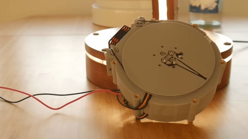
The motor reducing mechanism was the biggest challenge: most quasi-direct drives use a planetary gearbox, but this would have been difficult to 3D-print without either serious backlash or limited torque. A cycloidal drive was an option, but previous printable cycloidal drives seemed to have low efficiency, and they didn’t want to work with a strain-wave gearing. Instead, he decided to use a rope drive (this seems to be another name for a kind of Capstan drive), which doesn’t require particularly strong materials or high precision. These normally use a rope wound around two side-by-side drums, which are difficult to integrate into a compact actuator, but he solved the issue by putting the drums in-line with the motor, with two pairs of pulleys guiding the rope between them in a “C” shaped path.
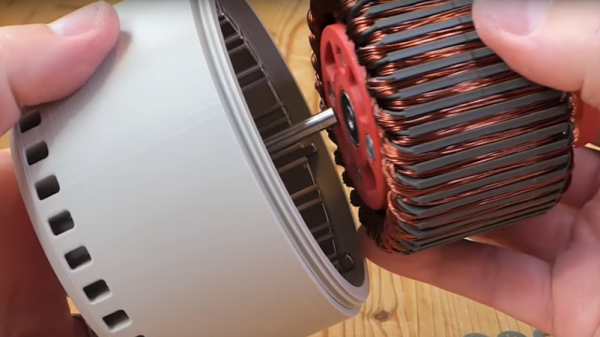
The actual motor is a hand-wound stator inside a 3D-printed rotor with magnets epoxied into it. The printed rotor proved problematic when the attraction between the rotor and magnets caused it to flex and scrape against the housing, and it eventually had to be reinforced with some thin metal sheets. After fixing this, it reached five Newton-meters of torque at one amp and nine Newton-meters at five amps. The diminishing returns seem to be because the 3D-printed pulley wheels broke under higher torque, which should be easy to fix in the future.
This looks like a promising design, but if you don’t need the output shaft inline with the motors, it’s probably easier to build a simple Capstan drive, the mathematics of which we’ve covered before. Both makers we’ve previously seen build Capstan drives used them to make robot dogs, which says something for their speed and responsiveness.
Not satisfied with the specs of off-the-shelf brushless DC motors? Looking to up the difficulty level on your next quadcopter build? Or perhaps you just define “DIY” as rigorously as possible? If any of those are true, you might want to check out this hand-wound, 3D-printed brushless DC motor.
There might be another reason behind [Christoph Laimer]’s build — moar power! The BLDC he created looks more like a ceiling fan motor than something you’d see on a quad, and clocks in at a respectable 600 watts and 80% efficiency. The motor uses 3D-printed parts for the rotor, stator, and stator mount. The rotor is printed from PETG, while the stator uses magnetic PLA to increase the flux and handle the heat better. Neodymium magnets are slipped into slots in the rotor in a Halbach arrangement to increase the magnetic field inside the rotor. Balancing the weights and strengths of the magnets and winding the stator seem like tedious jobs, but [Cristoph] provides detailed instructions that should see you through these processes. The videos below shows an impressive test of the motor. Even limited to 8,000 rpm from its theoretical 15k max, it’s a bit scary.
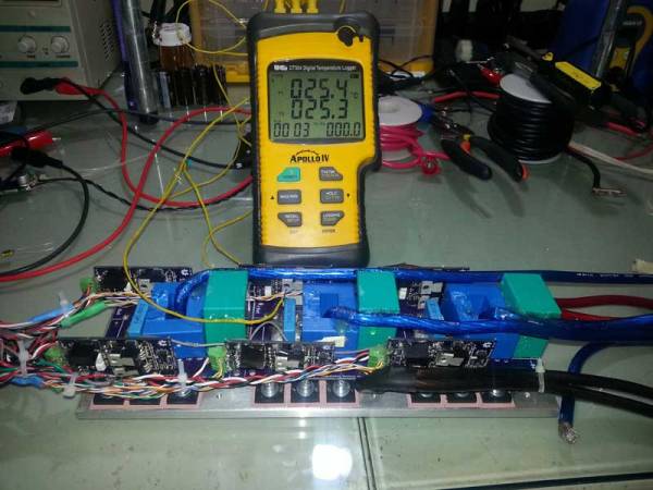
[ZombieSS] wrote in to share the latest iteration of his new open hardware Brushless DC motor high power output stage posted on the Endless-sphere forums. The thread is a gold mine of useful information on designing, building and debugging high power electronics and the whole thing is worth reading. This includes the story of issues he faced with common mode noise picked up by the probe leads on his Rigol, which sidetracked the project for a while.
We’ve covered various ebikehacks before, but the guys at endless sphere appear to be developing a number of solid open hardware designs in this area. This includes the Lebowski controller which [ZombieSS] used in conjunction with his design.
He has installed the controller and output stage on his electric bike, and you can see one of the first test runs in the video below. We look forward to hearing more from the awesome hackers at Endless sphere!
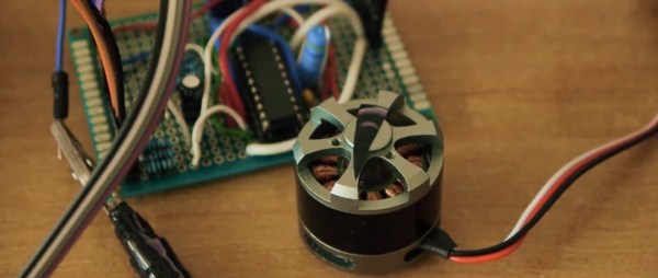
Driving a brushless DC (gimbal) motor can be a pain in the transistors. [Ignas] has written up a nice article not only explaining how to do just this with an Arduino, but also explaining a little bit on how the process works. He uses a L6234 Three Phase Motor Driver, but points out that there are other ways to interface the BLDC motor with the Arduino.
A warning is warranted – this is not for the faint of heart. You can easily destroy your microcontroller if you’re not careful. [Ignas] added several current limiting resistors and capacitors as advised in the application note (PDF warning) to keep things safe.
Everything worked well at high speeds, but for slower speeds the motor was choppy. [Ingus] solved this riddle by changing over to a sine wave to drive the motor. Instead of making the Arduino calculate the wave, he used a look up table.
Be sure to check out his blog for full source and schematics. There is also a video demonstrating just how slow he can make the motor move below.
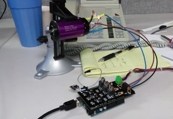
Brushless motors are ubiquitous in RC applications and robotics, but are usually driven with low-cost motor controllers that have to be controlled with RC-style PWM signals and don’t allow for much customization. While there are a couple of open-source brushless drivers already available, [neuromancer2701] created his own brushless motor controller on an Arduino shield.
[neuromancer2701]’s shield is a sensorless design, which means it uses the back-EMF of the motor for feedback rather than hall effect sensors mounted on the motor. It may seem strange to leave those sensors unused but this allows for less expensive sensorless motors to work with the system. It also uses discrete FETs instead of integrated driver ICs, similar to other designs we have covered. Although he is still working on the back-EMF sensing in his firmware, the shield successfully drives a motor in open-loop mode.
The motor controller is commanded over the Arduino’s serial interface, and will support a serial interface to ROS (Robot Operating System) in the future. This shield could be a good alternative to hobby RC controllers for robots that need a customizable open-source motor controller. The PCB design and source code are available on GitHub.
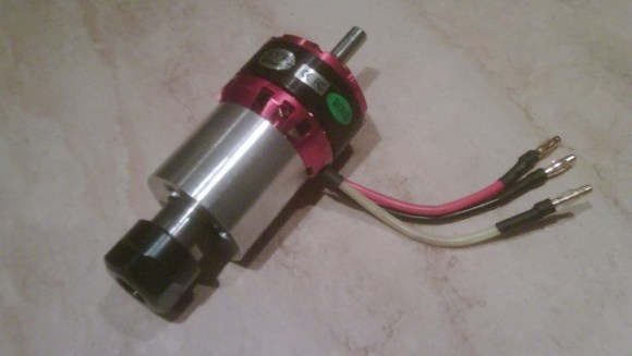
Brushless DC motors are common place in RC Vehicles. They are small, light, fast and can be inexpensive. [Raynerd] wanted a new spindle for his CNC machine and thought that a brushless DC motor would be a great platform to build from.
[Raynerd] started with an off the shelf motor that had an 8mm shaft. This shaft size was important because the motor shaft was to be replaced with an ER16 collet arbor of the same size. A collet is a device used to hold cutting tools by collapsing a segmented ring around the tool. Collets allows for quick tool changes while providing a strong clamping force. ER16 is a designation of one of many collet standards.
The main housing was machined out of aluminum specifically for this project. This housing holds two radial load ball bearings that support the new rotating collet arbor. There’s another bearing in this assembly, a thrust washer this time, that keeps the arbor from moving axially in the housing.
The 12 volt output of a standard ATX power supply was used to power the system for testing purposes. A general RC Vehicle electronic speed control and a servo tester work in conjunction to manually regulate the spindle speed. Check out the bench test video and an exploded photo after the break.


 A warning is warranted – this is not for the faint of heart. You can easily destroy your microcontroller if you’re not careful. [Ignas] added several current limiting resistors and capacitors as advised in the