
This post is a continuation of yesterday’s post:
Yesterday’s post was inspired by Dr. Paul Wilhelm’s post on this subject:
Well, I can’t leave well enough alone whenever a predecessor from history (Graneau, Ampere, etc) performs an experiment and gets anomalous results whether or not he recognized it at the time. If it’s recognized, now, then that’s good enough for me to investigate the possibility to see if I can “milk” this for what it’s worth. Who knows? Maybe it’ll yield something interesting?
Yesterday’s simulation looked like this:
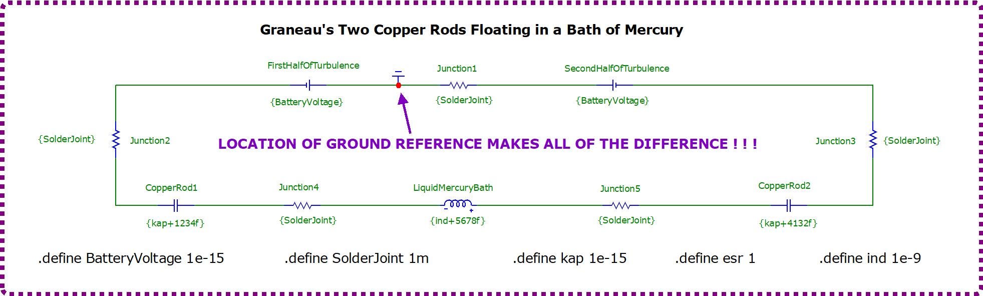
And it gave this result:
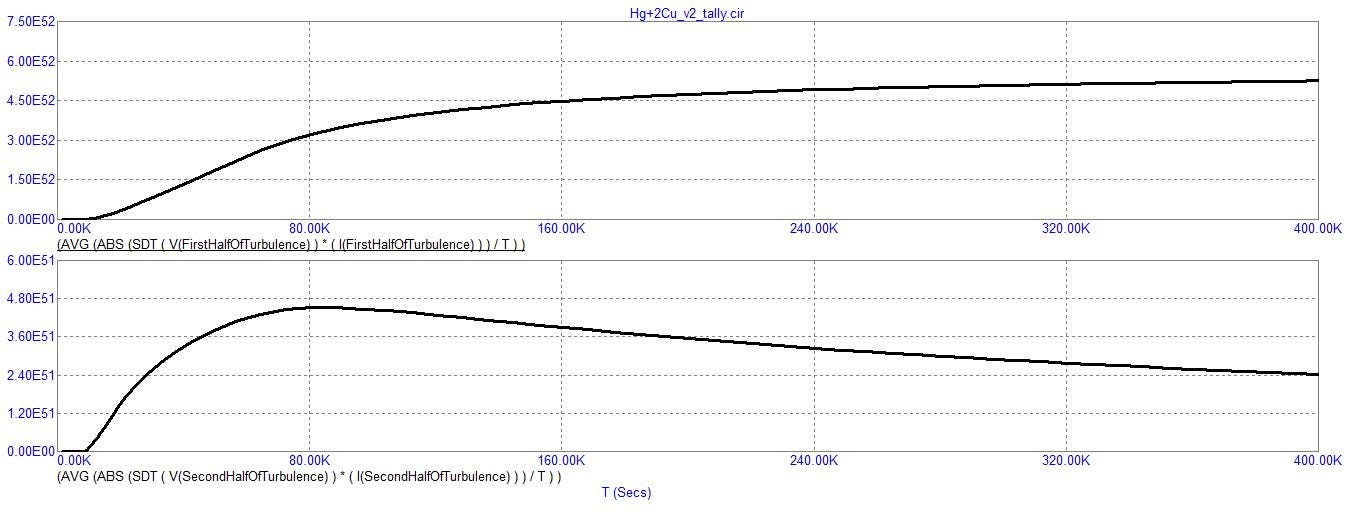
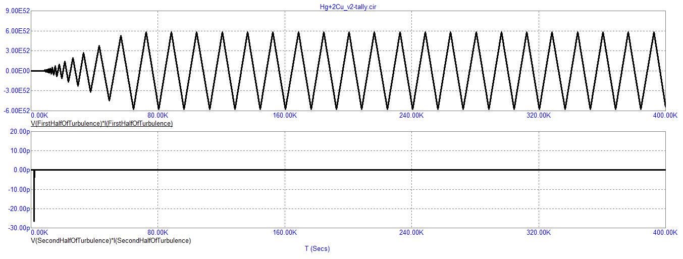
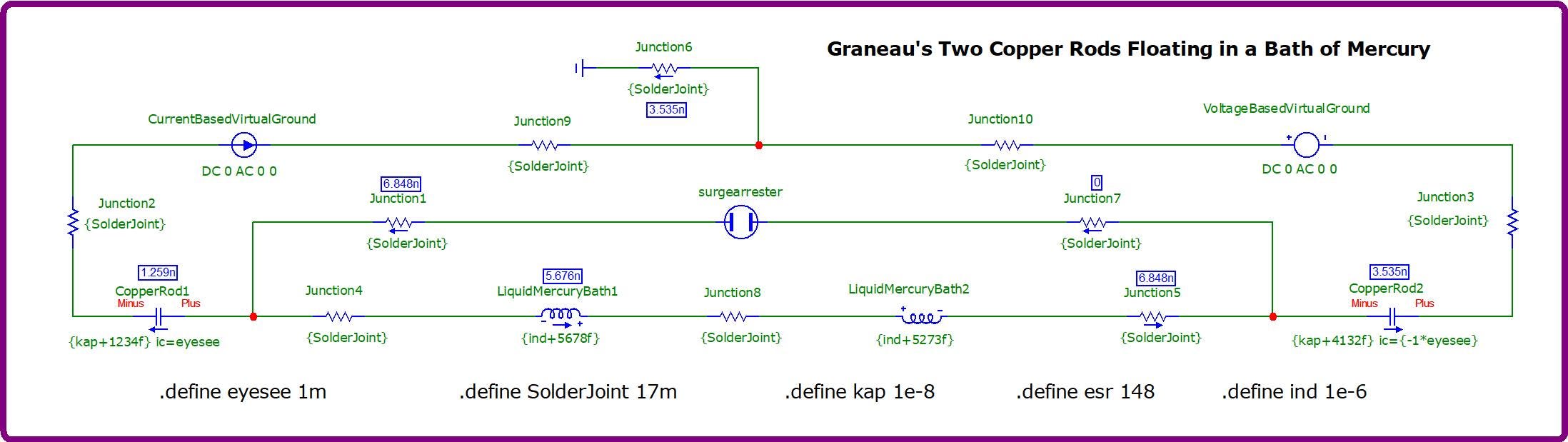
Today’s endeavor looks like this:
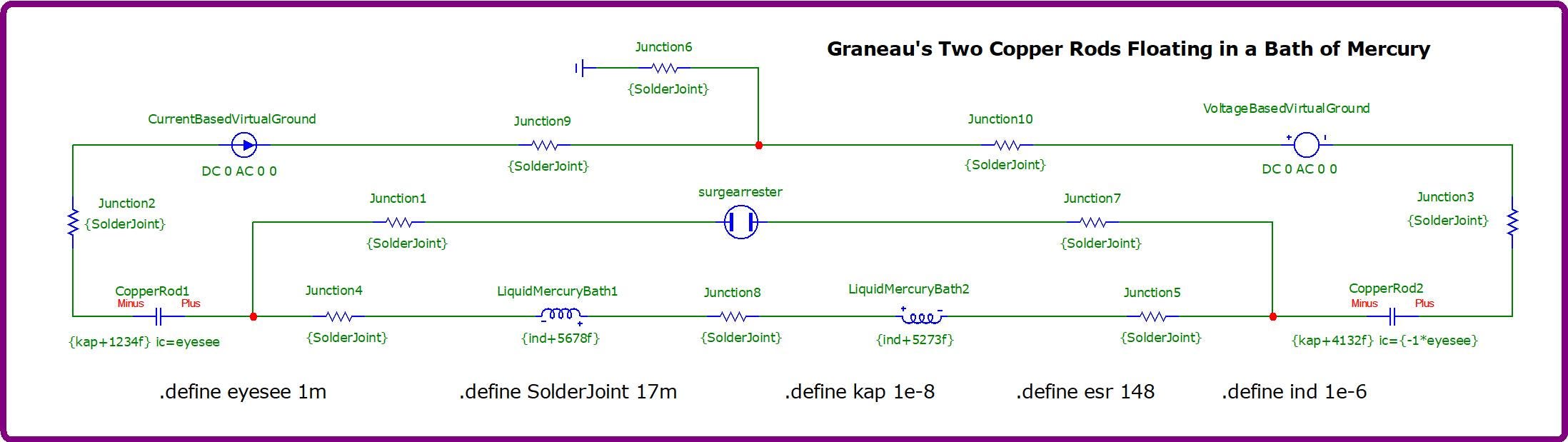
And it gives this result:
I had to run a simple test, first (at some point in the development of this latest version of being inspired by Graneau and Dr. Wilhelm) to remind myself of the direction of current for both voltage and current sources whenever they’re in D/C mode:
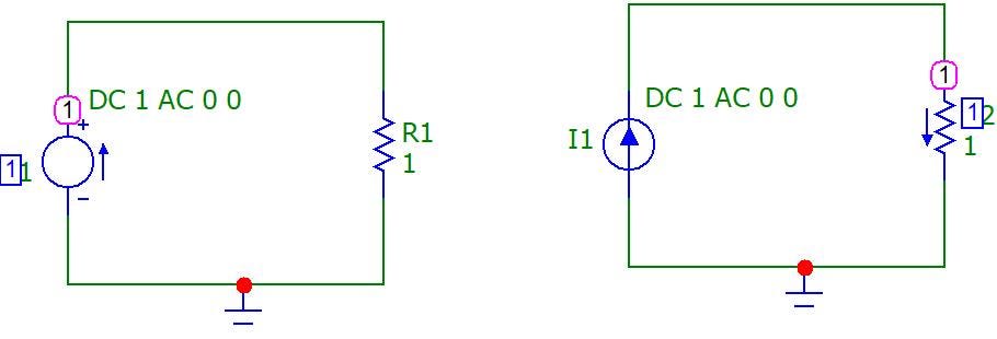
… so as to know what orientation to use when applying these two components as zero input sources to substitute for the two opposing batteries of yesterday’s experiment. Today’s experiment is missing a ‘source’ to stabilize its behavior. So, I grabbed these components to perform a similar service and placed them in the same place as the missing pair of batteries since the circuit doesn’t need a ‘source’ anymore since I have this habit of falling back onto precharged capacitors for all of my free energy input circuit simulations.
To determine orientation, ie: polarity orientation, I ran a short simulation (first) without these zero sources and mapped current direction similar to (but not the same as) this example:
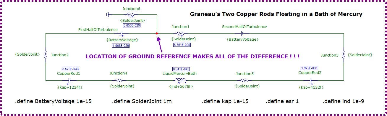
I wanted to take advantage of the natural tendency of the circuit’s preexisting current pathway vectors so that when I inserted my zero magnitude input sources, then they won’t “fight” the natural flow, but instead, reinforce it — even though they won’t be contributing any current at all. Nonetheless, I wanted to make believe that if current were to flow from out of these ‘sources’, that any potential for a conflict should be prevented from existing.
And I wanted these two sources to contribute zero input so as to serve as ‘virtual grounds’.
By the way, a virtual ground is a node which is near zero, without necessarily being exactly at zero, and doesn’t change the amplitudes of its voltage or current phases very much over time.
For all intents and purposes, this can serve as an alternate or extra ground reference.
Here’s the paths which the currents take of today’s circuit:
Here are the nodal voltages:
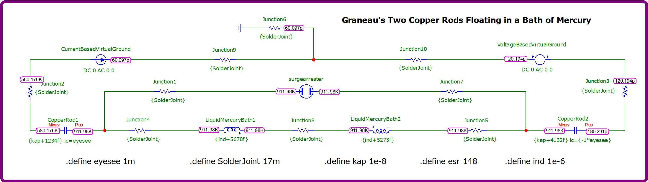
And the powers:
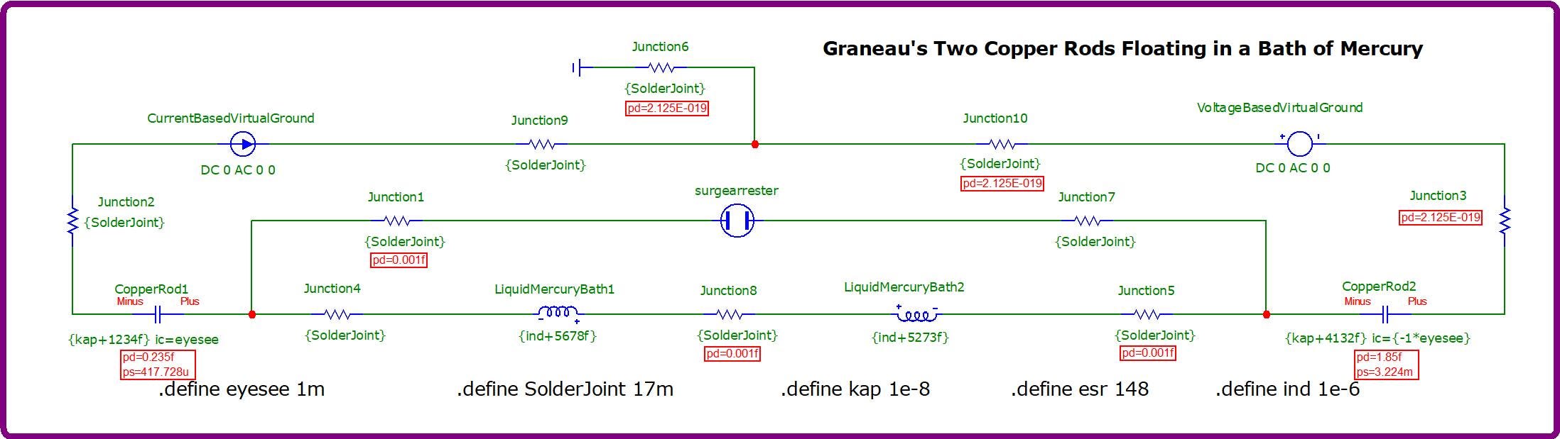
In these examples, the resistances, capacitances and inductances are as high as they can be without collapsing these results into a comatose condition yet be able to slow down the escalation of these amplitudes to as slow a crawl as is possible.
What these numbers are telling me is that this circuit cannot — in its present condition — be said to be carrying any substantial load since all it is capable of exhibiting is the ability to accumulate nodal voltages. Thus, its power and its currents are very small.
Yet, maybe if we added a load in an appropriate location, maybe it would wake up and deliver current and power under the demand imposed upon it of this load?
Let’s see… Where should a load be placed?
… snipped
I curtailed my investigation a little bit after this point since it led to a dead end in so far as this circuit is not suitable for anything other than blowing itself up since its simplicity doesn’t allow for any sophisticated regulation.
Not that I didn’t try to regulate it.
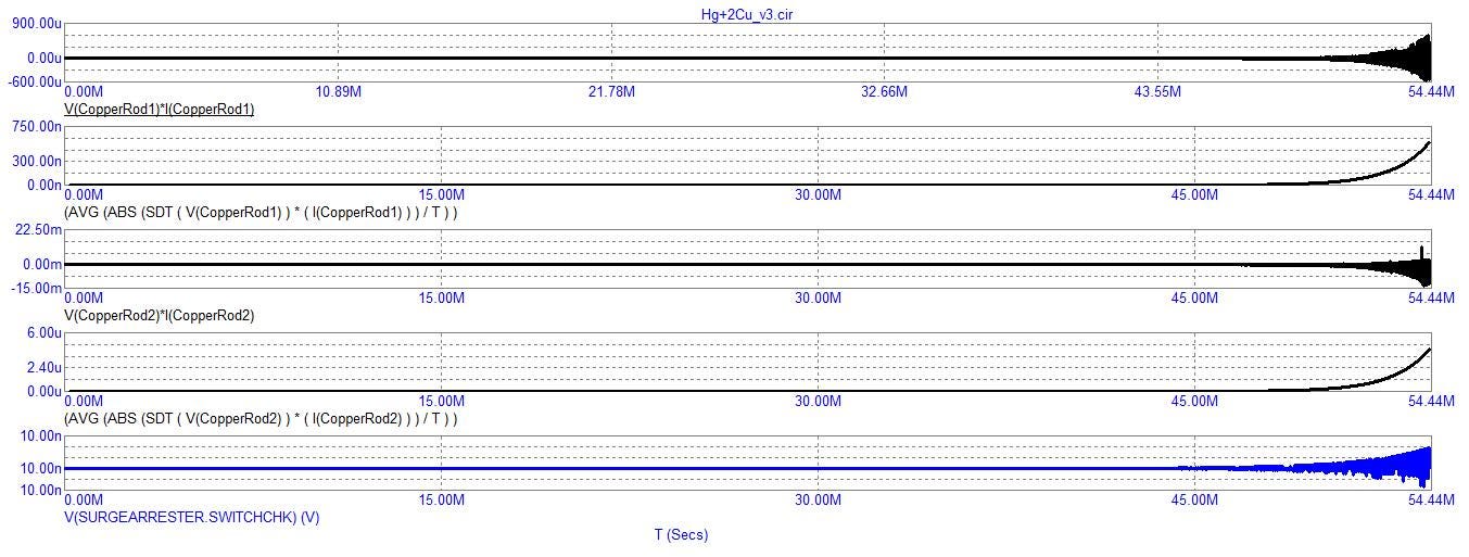
You’ll see in a second what I mean. It slowly escalates in a nice curvaceous hyperbolic curve toward infinite gain.
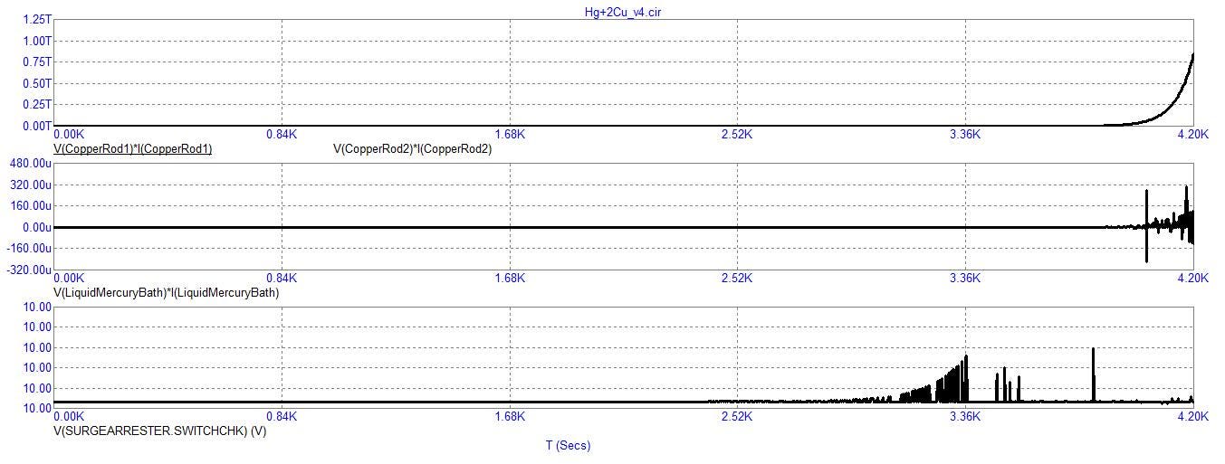
But eventually, it vertically shoots upwards and downwards towards positive and negative infinity after first pursuing that nice curvaceous climb outwards from the zero midline of its virtual oscilloscope tracing.
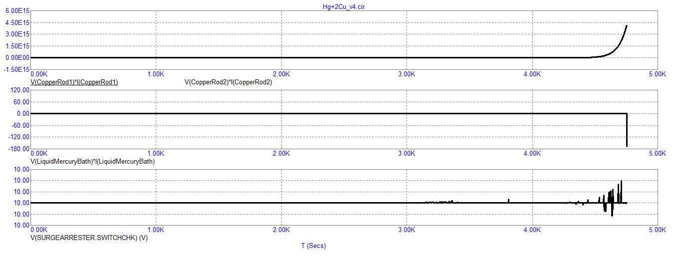
Here are the nodal voltages, the currents, and the powers of a 4.2ks runtime before it vertically explodes:
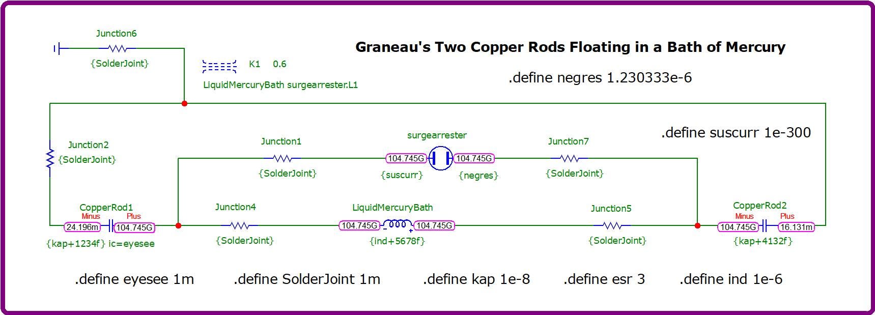
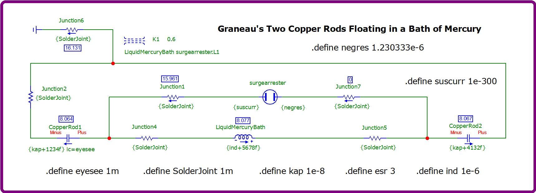
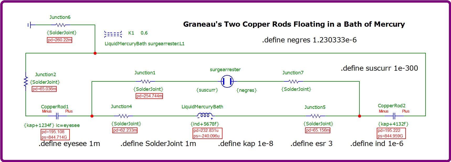
By magnetically coupling the outer coil, “LiquidMercuryBath”, to the inner virtual coil of the “surgearrester” using the “K1” statement: “LiquidMercuryBath surgearrester.L1 0.6”, it was possible to tame this animal to some limited degree. But ultimately, I don’t think that this simple topology can be tamed unlike either of my previous simulations which could be tamed, such as:
Download this last circuit experiment from my website or from my Google Docs account.
Comments
Nothing yet. Say the first thing.
Sign in to join the conversation.