
I like to keep my feet on the ground, as I think that’s down, and everything falls “down” there, as far as I know. Things don’t fall Up, last I knew. Although some might disagree.
Well what about the Australians and South Americans? Believe you me, they have their own problems, and they know we’re upside down . . . but be that as it may.
So I’d like to chew on a few obvious (to me, at least) rules of reality.
First off: the Inverse Square Law.
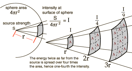

This is the typical exposure scenario of light emitted from a candle, or the Sun at a great distance, or an Omni-directional antenna (the omni, for those who din’t know, means in all directions), a mobile phone is Not omni-directional. What may not be obvious from the sketch, and due to little detail to prevent clutter, the first grayed out block within the sphere sits on the surface of the square. So anyway, despite the formula, what you should get out of it is the proportionality ratio of 1/r^2, meaning that whatever you measure at r, at 2r it will be 1/4 of that at r, at 3r it will be 1/9 of that at r, and so on. Enough of that, I think you get the point. BTW this is a classical Point Source.
Secondly: the Inverse Linear Law
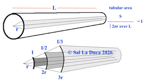
This is the typical exposure scenario from a power line. As long as you walk parallel to it, you measure the same intensity “I”. But as you walk away from it, the intensity is now complemented by every other point on the line, so that now if you go twice the distance “r” the intensity is 1/2, if you go three times the initial distance the intensity is now 1/3, and so on. This produces a proportionaly ratio of 1/r. For the curious lot among you, that formula is the Integral of the exposure on the surface of the circle, but extrapolated over the entire length L. The formula holds for any length “L” much greater than human dimensions. As the L gets shorter and shorter, then the formula approaches the Inverse Square Law. I haven’t seen it explained clearly anywhere, and this is my attempt at it with mediocre graphics. Like or dislike it if you will, but it is reality. This is a classical Line Source, and is typical of Power Lines, Neutral interconnections to neighborhood metallic piping, etc.
Now we step into murky reality show.
Some engineers have promoted an inverse cube law. Their claim is that some sources exhibit this, without pointing out that those sources have non-symmetrical emissions, and taking measurement at any point is space the same distance from the source, you’ll get different readings.

The above is a source with non-symmetrical emissions. It’s been on my business card for about 30 years and reflects the field from an Alternator, a Shaded Pole Induction Motor (this costing a dime a dozen to manufacture and employed in “sleep sound machines”, desktop fans, refrigerators, microwaves, bath exhausts, etc.) and which produces a signature of some 10 feet in diameter, DEPENDING on how it’s oriented. So the most you could say is that the emissions are non-symmetrical (or the same), at all equi-distant points from the source, NOT that it follows an inverse cube law. Even a casual glance at the first graphic, should make it obvious that the inverse cube law does not follow the laws of our physical universe, and if indeed it exists, includes other variables not particularly relevant to electromagnetic fields. So those engineers that promote the inverse cube law should get a real job, where they can do less damage. You may know who they are.
The following is a brief discussion of a Breaker Panel as a source of Magnetic fields from Current flow.
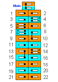
A breaker panel may look like the above, and its breakers are typically numbered as shown. However, this omits something obvious, the internals.
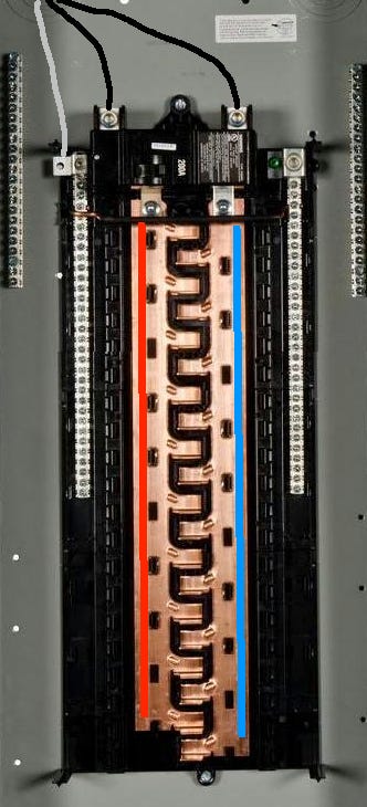
I have taken the liberty of “chalking in” current flow paths in Blue and Red on the two respective bus bars. The more centrally located “fingers” are what individual breakers snap onto. Note the difference from the top to the bottom. I know you may not see it, but bear with me. Most individual breakers are rated 15 or 20 Amps, but usually never carry that full capacity, so the respective sections of the lower bus portions carry a small aggregate of the total of those local breakers. As you approach the top, the bus bars will carry aggregate currents from the additional breakers along the way easily summing to 15 to 50 Amps or more, per bus. As a point of reference a typical 200 Amp panel can carry up to 200 Amps per bus bar. This presents a problem that CANNOT be “engineered away.” From an immediate safety perspective, all is working fine. However, from an Alternating Magnetic Field (some call it “EMF”), the bus bars (and specifically the current paths therein) being perhaps four inches apart produce a Magnetic field signature (because of the separation) right through the metal backing and any adjacent wall, as well as right through the front. And no, Lead sheeting will Not stop it. As I said you can’t engineer this away, nor can you apply any magnetic, or “magic” amulet that will “reduce it,” “minimize it,” “harmonize it,” or otherwise. It is what it is.
Slicing horizontally across the panel and looking down, or up if you prefer, the magnetic fields from the bus bars may look like this. It will be smaller near the bottom of the bus bars, furthest from the main input wiring shown at top.
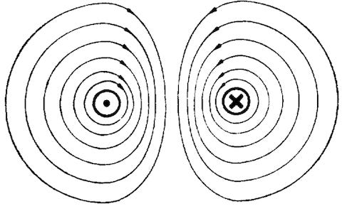
It will be pulsating at 60 Hz (+ whatever Harmonic frequencies you are producing, which also Cannot be engineered away, and are really, Really, much worse that what those “dirty electricity” filters, you may have bought and use, claim to “fix”), and its dimensions will vary over time depending on the amount of current in use at any point in time.
BUT, taking a closer look at the same horizontal slice,
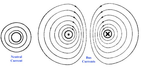
you can see that the Neutral current adds a bit of complexity. I have purposely not shown a polarity to the neutral, as it will vary dynamically with the usage on the different buses. As a “Normal” result, if bus A current is say +40 Amps, and bus B is -25 Amps, the Neutral current will be -15 Amps, so that if you placed a current clamp around all three wires simultaneously you would Always detect zero current.
BUT, and this is a big but, if your power system is of an apartment or if it is connected to a neighborhood metal plumbing supply, then the neutral can have anywhere from zero to 20+ Amps to or from sources external to your system, producing an unrestrained Alternating Magnetic Field . . . Kill / open / turn off your main breaker and that Neutral Stray Current will still be there.
If confronted, your electrician will quickly tell you that in his 30 years of doing this kind of work he’s never seen this . . . Either we live in a different universe, or they do.
When the neutral Stray current is not considered, you can live in this environment,
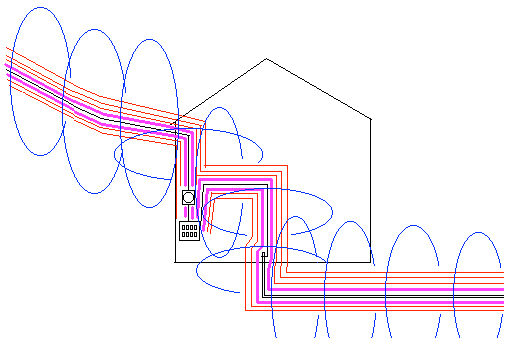
acquire a terminal disease, and no one is the wiser. Because after all, who knew you were sleeping next to a power line. And of course, most electricians have never seen this . . .
So a colleague / friend saw a video blip of someone “neatening” the hots and neutrals for each branch to reduce the panel’s M field. Nice idea, but, owing to the above two expositions, while neatening the wiring will make it easier to ever do subsequent work, as a means of reducing the M fields, or their aggregate, it is chasing after wind.
There is yet another snag related to the panel, a wiring error between two or more circuits.
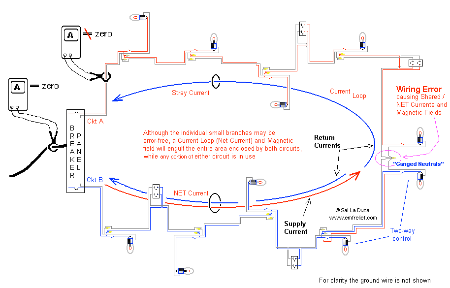
The above describes two circuits whose neutrals are tied together (ganged), somewhere beyond the panel. The error will cause non-zero currents in each branch (as they should be, since supply and return currents are supposed to be equal, and if so a current clamp will always detect zero) and a Magnetic field that envelops a room, rooms, or the entire home, depending on the circuits and error location. This field’s intensity varies depending on what is in use, such as a fan, or a hair drier, as examples.
Of course there are solutions to the Neutral Stray Current and the internal wiring error just described, and while the best people to employ those solutions are electricians (and marginally a plumber (but they’ve got problems too)), it’s difficult to get any to do so, ‘cause they don’t want to get their fingers dirty fixing other electricians’ work. Additionally they may need to re-learn the crucial difference between Bonding and Grounding, which is most difficult to do when they’ve already reached “perfection.” After all, they’re professionals, licensed, and bonded.
This does not cover the Electric fields from said wires . . . also EMFs! And then, there are those who suggest Romex to be the best wiring to prevent EMFs, and adding that a few twists of the cable, with a drill if you wish, will reduce EMFs further . . .
Along plumbing lines of thought, consider the word dielectric. The dictionary briefly defines it as anything electrically non-conductive.
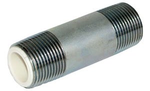
The above is commonly sold as a dielectric in most hardware stores across N. America. Please give it some thought, and try to imagine How the plastic internals will stop current flow.
Then consider the following.
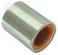
The plastic internals on this one are threaded on both ends. Guess which of the two is a true dielectric. Then guess which of the two a plumber will install if asked . . .
If a true dielectric is properly installed, then there is an additional item that needs to be considered, but since none of you have this problem, I will not mention it here.
Food to thought!
Cheers,
© Sal La Duca, 2026
No posts
Comments
Nothing yet. Say the first thing.
Sign in to join the conversation.