
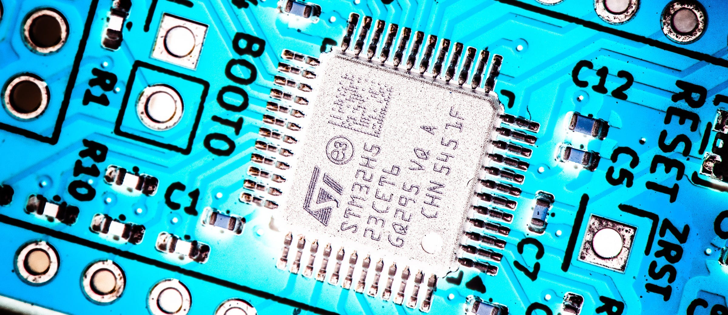
Following the age-old principle of ‘if it ain’t broke, see if you can break it’, I decided to have another crack at the PCB for the McROM, a microcontroller-based replacement for the EEPROM in my Zolatron 65C02 homebrew computer.
The McROM is based on an STM32H523CET6 microcontroller humming along at an impressive 250MHz. It has more than enough GPIOs to handle the address bus, data bus and control signals. The idea was to have a board with the same footprint and pinout as the 28C256 EEPROMs I’m currently using as ROMs in the Zolatron so that I could drop the McROM straight into the socket that already exists on the main processor board. The advantage would be that I can reprogram the device without having to remove it from the Zolatron — indeed, without even having to turn off the computer.
In the first article in this series I detailed the board design and the ideas behind it. In the second article I covered the STM32 firmware and also some of the issues I encountered.
At the end of that second article I had a device that was (mostly) working, and which at least proved the concept. But this was my first STM32 project and, inevitably, there were challenges and mistakes. For one thing, I ended up soldering eight pull-up resistors to the board in a manner that could be politely described as ‘iconoclastic’. But I’m not polite so let’s call it an ugly bodge.
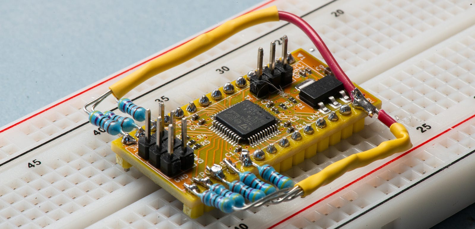
Fortunately, PCBWay supports this publication by providing free PCBs, so I took the opportunity to do a respin. Let’s look at what changed.
Comments
Nothing yet. Say the first thing.
Sign in to join the conversation.