
The complete analysis of:
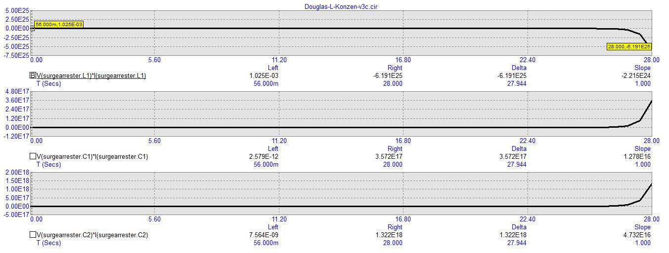
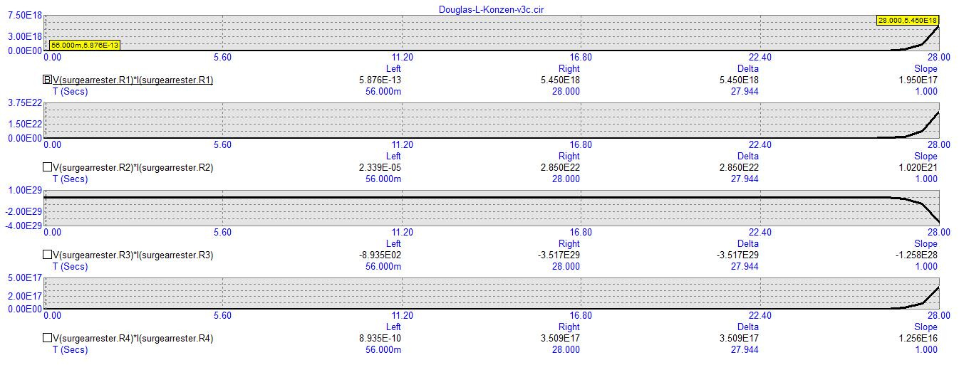
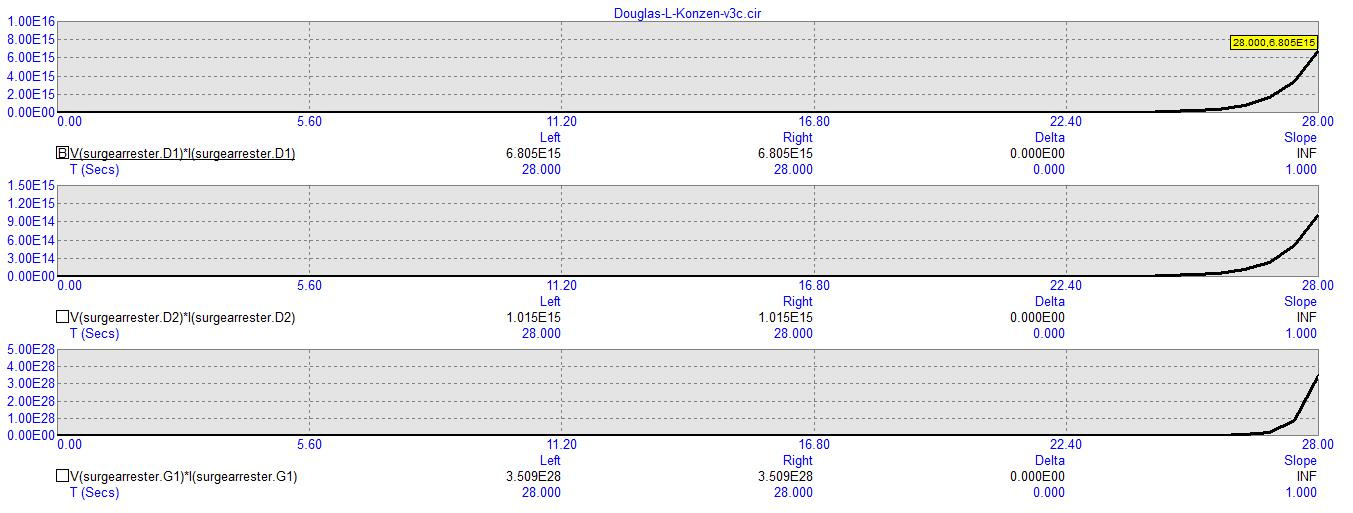
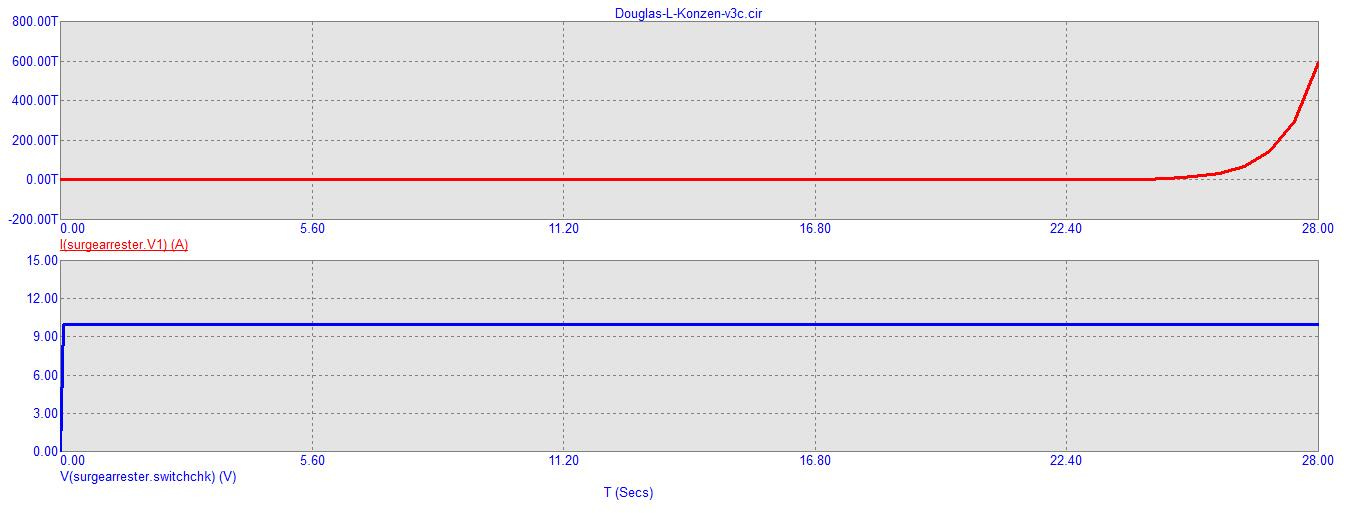
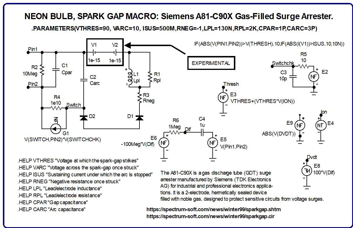
In this version, I cannot include the wattage of the zero-voltage battery (that is inside of the macro for the surge arrester) since zero volts renders as zero watts. Yet, the current passing through this component is very high.
But we can scope the paths which the current takes across the circuit’s schematic:
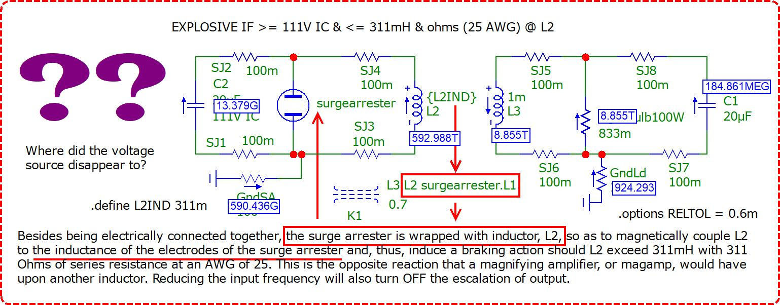
Notice how the current is traveling into this circuit through its two grounds, GndSA and GndLd. That’s pretty cool.
And we can look at the paths which the current takes across the spark gap macro for the surge arrester that is being used by this circuit simulation:
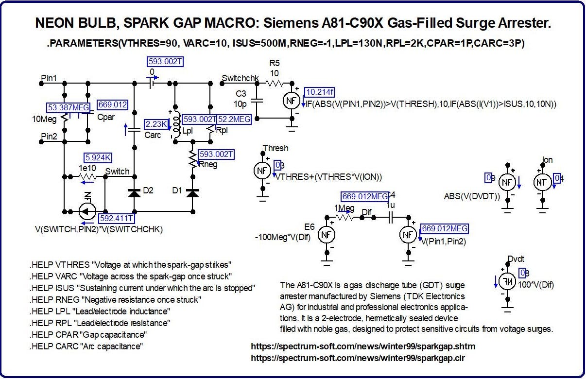
That’s a lot of current passing through the zero-voltage battery, V1, up-above. Is any of that current coming from the battery? Or, is it merely passing through it from elsewhere?
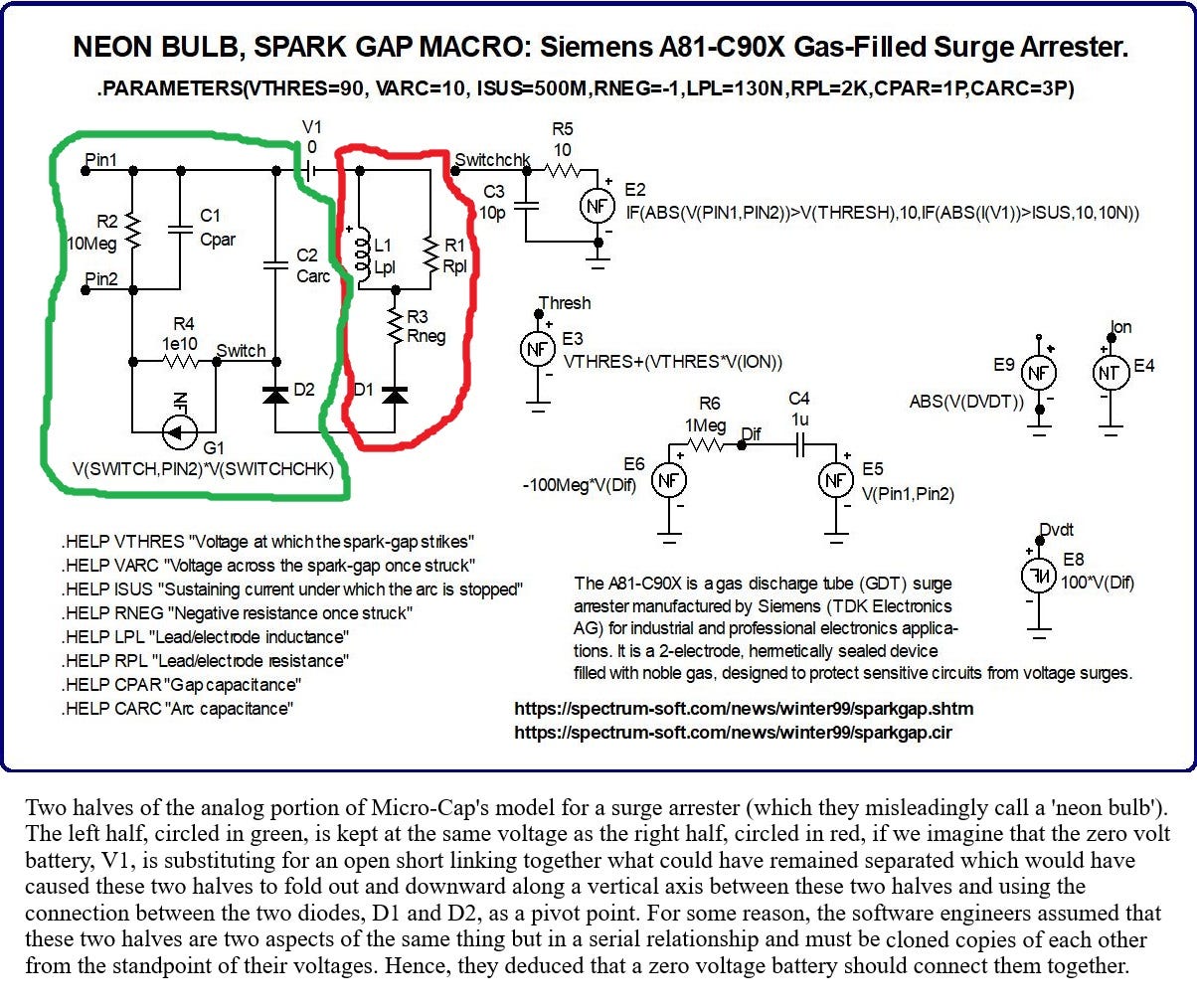
It’s almost as if this zero-voltage DC source was intended to tie two halves together (lying on either side of this circuit) as if they were one entity modeled in parallel with each other and maintain the same voltage (between these two halves) by tying them together with a zero-voltage DC source.
But since I’m curious whether this component is contributing any wattage, and I can’t tell what its wattage is since its voltage is zero (despite its elevated current depicted in the screenshot up-above), then I will include two deviations (within the compressed ZIP file) to see if I can evince a wattage from out of this component. — [I couldn’t.]
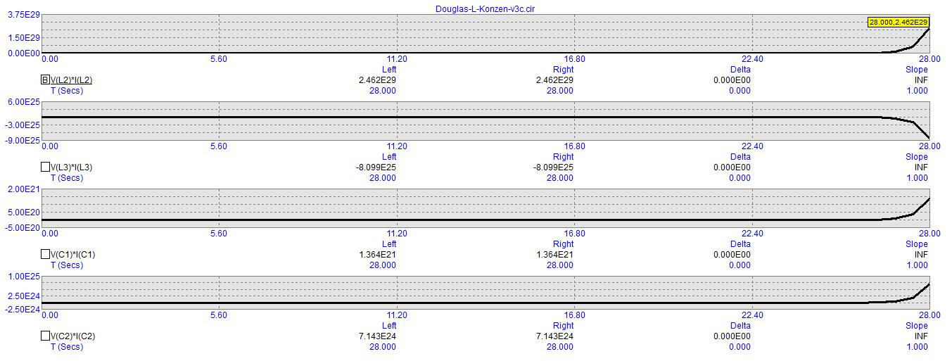
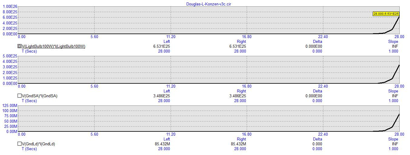
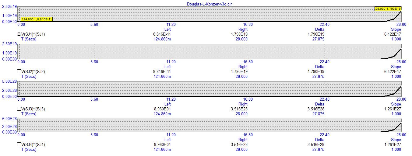
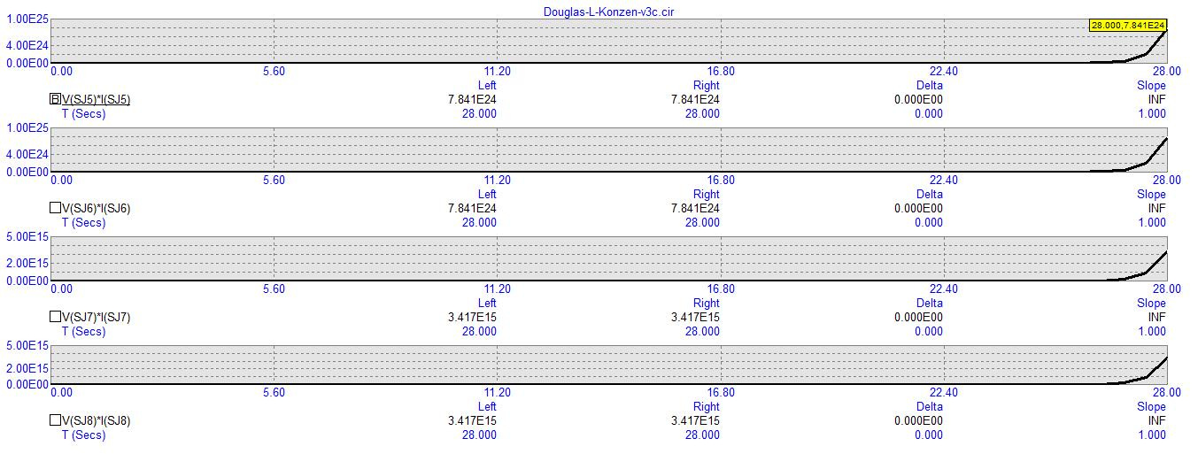
But, as it stands, and without the wattage from this component, here are the subtotals and the grand total of the wattages of all of the components of this circuit simulation which contribute towards its total outcome using the data from the screenshots, up-above.
+2.462e+29 = L2, Fig. #1
+1.364e+21 = C1, Fig. #1
+7.143e+24 = C2, Fig. #1
+6.531e+25 = LightBulb100W, Fig. #2
+3.486e+25 = GndSA, Fig. #2
+8.5432e+7 = GndLd, Fig. #2
+1.79e+19 = SJ1, Fig. #3
+1.79e+19 = SJ2, Fig. #3
+3.516e+28 = SJ3, Fig. #3
+3.516e+28 = SJ4, Fig. #3
+7.841e+24 = SJ5, Fig. #4
+7.841e+24 = SJ6, Fig. #4
+3.417e+15 = SJ7, Fig. #4
+3.417e+15 = SJ8, Fig. #4
+3.572e+17 = surgearrester.C1, Fig. #5
+1.322e+18 = surgearrester.C2, Fig. #5
+5.45e+18 = surgearrester.R1, Fig. #6
+2.85e+22 = surgearrester.R2, Fig. #6
+3.509e+17 = surgearrester.R4, Fig. #6
+6.805e+15 = surgearrester.D1, Fig. #7
+1.015e+15 = surgearrester.D2, Fig. #7
+3.509e+28 = surgearrester.G1, Fig. #7
+351,733,024,907,294,754,000,085,432,000 = +3.517e+29 SUBTOTAL POSITIVE WATTS
-8.099e+25 = L3, Fig. #1
-6.191e+25 = surgearrester.L1, Fig. #5
-3.517e+29 = surgearrester.R3, Fig. #6
-351,733,024,907,294,754,000,085,432,000 = -3.517e+29 SUBTOTAL NEGATIVE WATTS
+351,733,024,907,294,754,000,085,432,000 WATTS
-351,733,024,907,294,754,000,085,432,000 WATTS
0 = TOTAL WATTS! ENERGY IS CONSERVED! YIKES! 😉
First of all, I’m totally shocked. I didn’t think it would add up to zero. But this is a clear indication of the accuracy of 64-bit computing since, when I performed this type of analysis on a much simpler set of circuits back in 2021, I could never come out to zero. It would either be greater than or less than zero but never exactly zero unless the circuit being analyzed and tallied was a simple flashlight circuit. But if the circuit had no voltage source, no current source, no behavioral source, and merely ran from a precharged capacitor, then my 32-bit laptop kept coming up with inequalities between the positive wattages and the negative wattages.
This is a good sign for 64-bit computers closing the credibility gap when it comes to simulating free energy circuits.
I won’t bother with the other two deviations since I’m lazy. But I’ll let you download their screenshots and perform your own calculations if you care to.
Their raw data is exactly the same except for the nearly zero-voltage battery in the spark gap macro has been modified to be the minimum voltage which the simulator can accommodate with its double-precision floating point system of enumeration.
This would be: +1e-15V = 1 femto volt, or one thousandth of a pico volt. This is the same as one millionth of a nano volt, or one billionth of one millionth of a volt.
Then I double this battery and face it towards its partner or away from its partner in these two variations of a zero-volt battery, spark gap macro, in order to cancel what little voltage is allowed to come out of it.
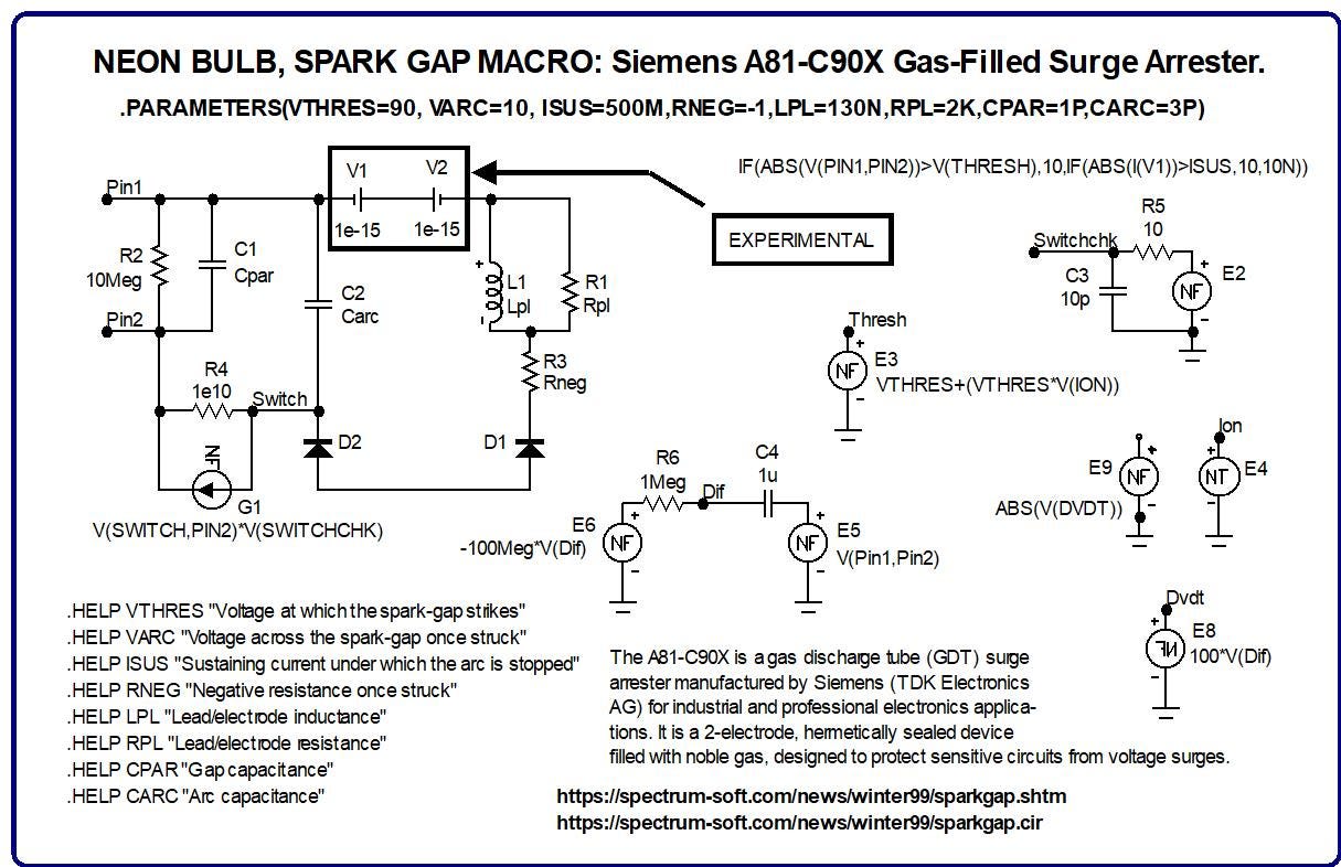
As you can see in these next two images:
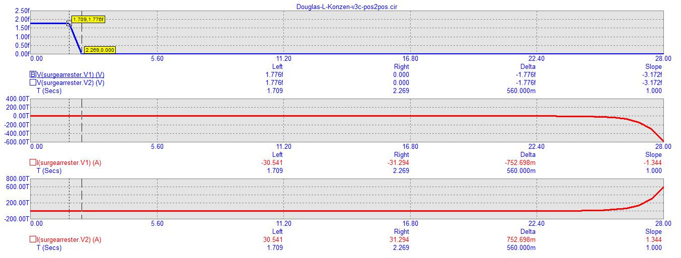
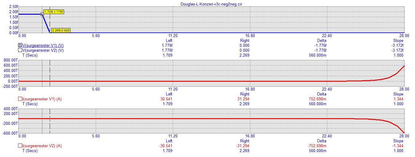
… the non-zero condition of these two (nearly zero-voltage) batteries gets pushed to zero volts, in approximately two seconds, due to the escalating current passing through it similar to how a wind can blow out a candle flame.
So, we still don’t get to include this type of component in our assessment of total wattage because the momentary appearance of voltage and wattage occurs before any significant escalation of current contributes towards an interesting gain of outcome.
Download this circuit’s files from my website or from my Google Docs account.
Comments
Nothing yet. Say the first thing.
Sign in to join the conversation.