
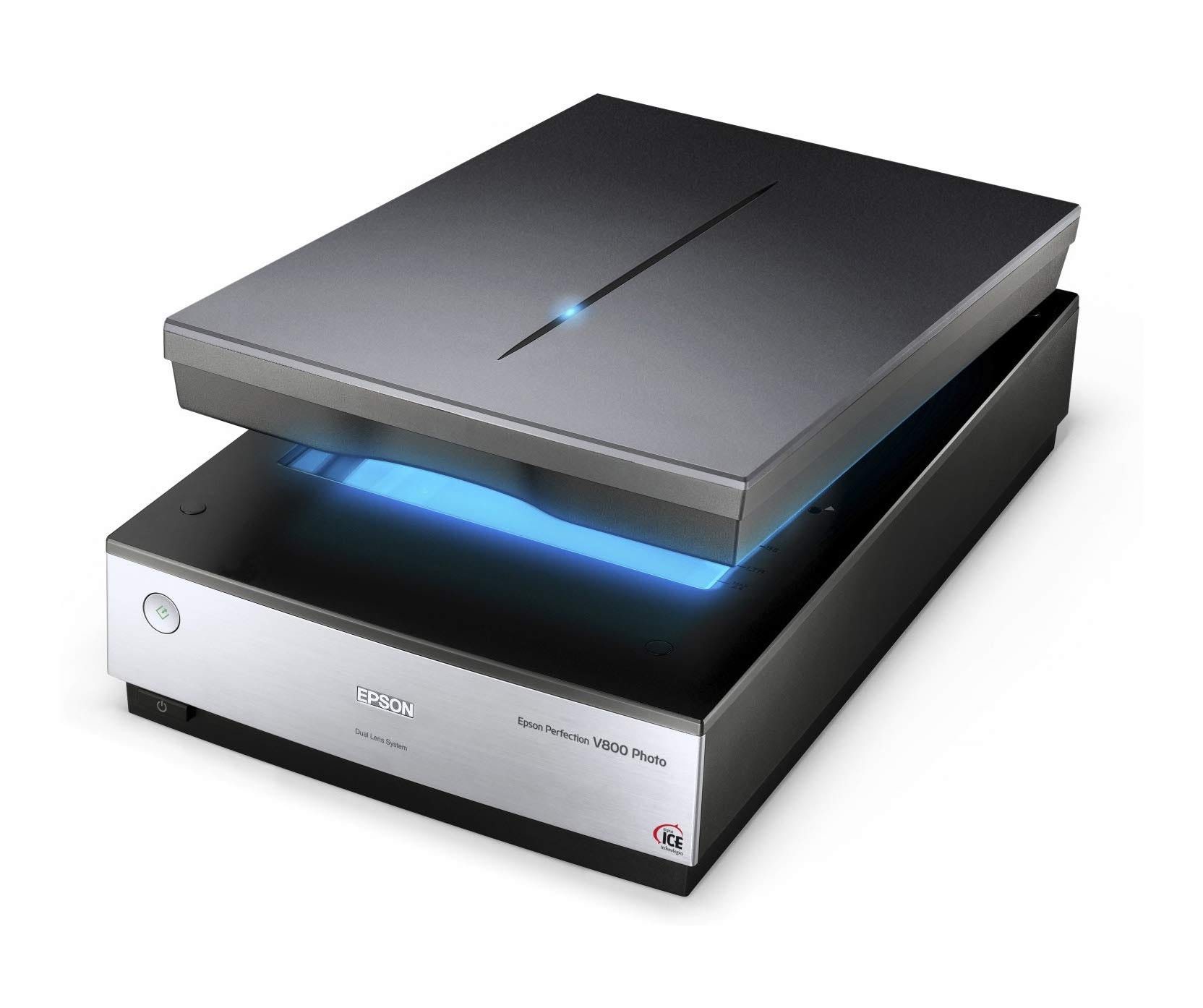
I had a customer bring in an Epson Perfection V800 scanner for repair. It was described as (at the time) inconsistently powering on, and was put on the shelf to gather dust for a few years. Now, it’s sitting on my bench in the hopes that it can be repaired.
The power supply had long been misplaced, so I was not able to immediately verify the problem was as described. However looking online, I found this post that seemed to describe similar symptoms. Looking at the unit on my bench, I could see the same odd looking centre contact on the barrel jack.
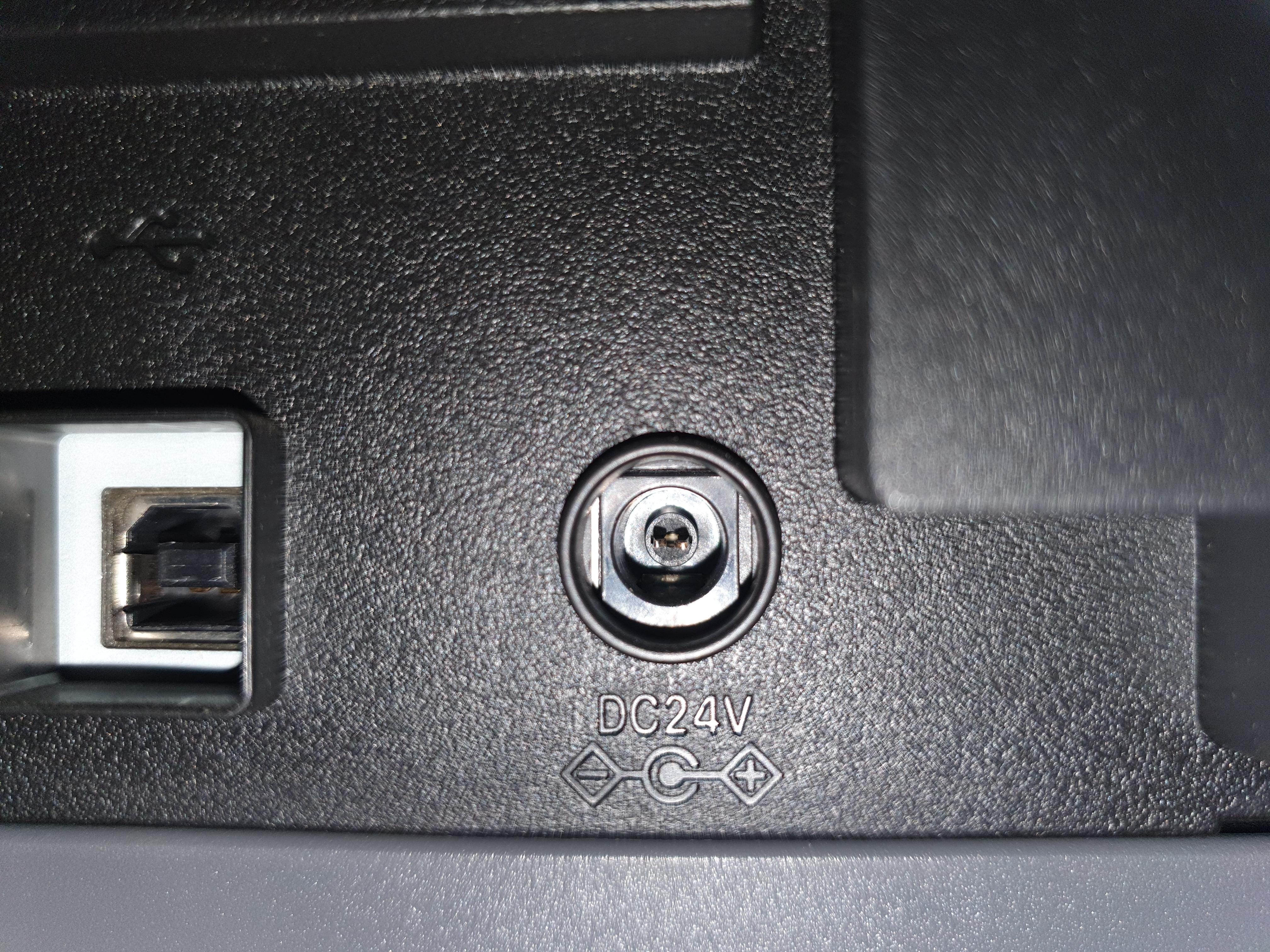
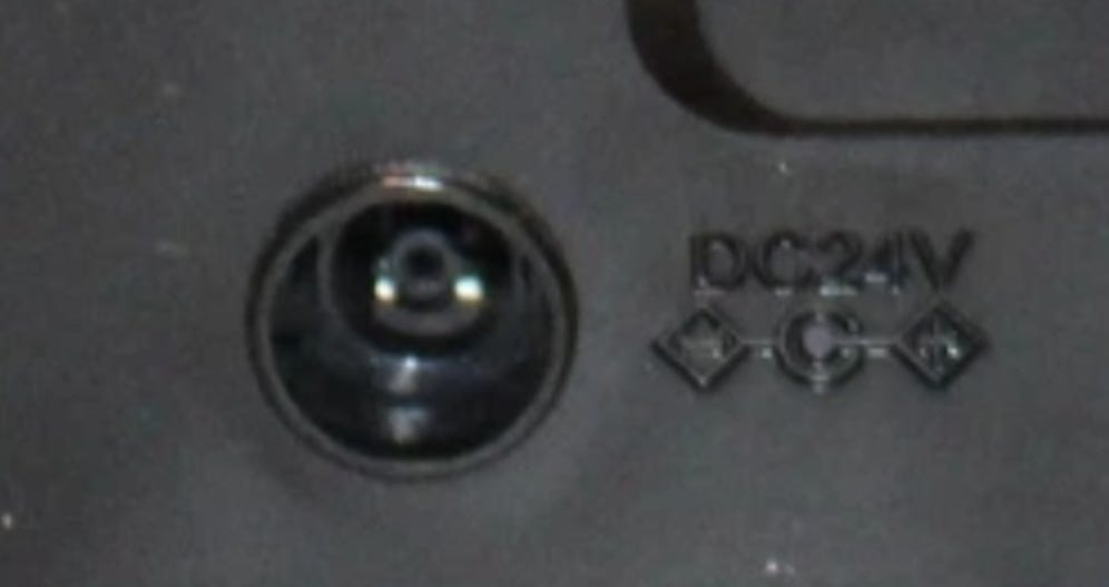
At first I thought this was just an odd, fork-style contact for a ‘standard’ barrel plug (normally these are a circular pin). However linked in one of the comments is a picture of what the jack should look like. Notice the missing (seemingly broken) plastic shroud in the centre:
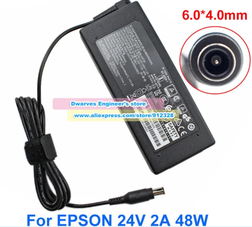
I managed to find pictures online of what the plug end looks like, and as can be seen, this is an obscure or proprietary plug with a pin in the centre rather than a receptacle.
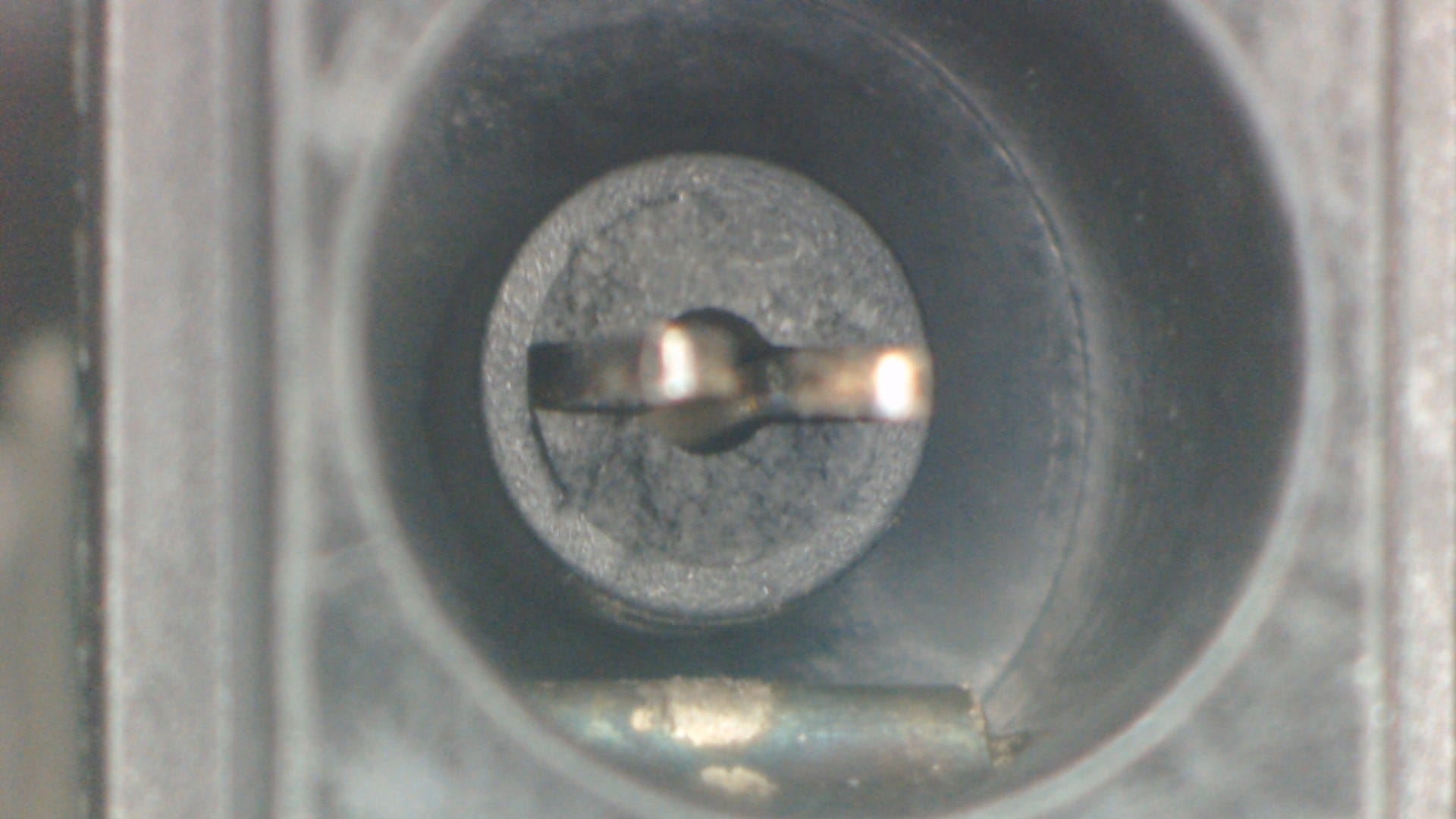
Removing the board, we can take a closer look at the damage inside the jack:
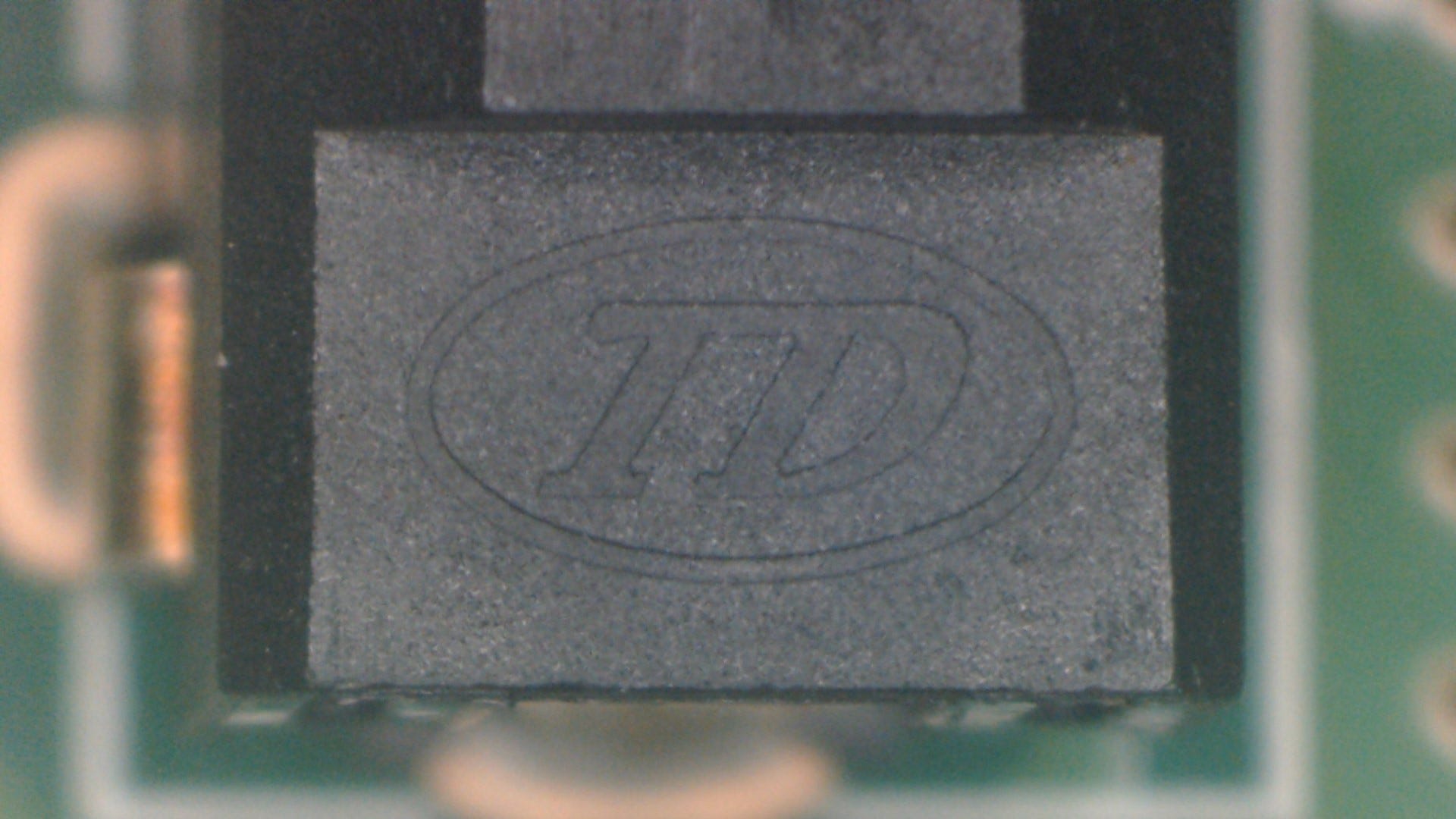
Looking at the top of the connector, there’s a manufacturer’s logo (TD), though not one I was able to recognise or track down.
Edit: I was able to eventually track down a potential match for the manufacturer; a Taiwanese component supplier subsidiary Taiduan Xingye Co., Ltd. Naturally, they have no online presence in ‘the west’, and thus this exact connector is likely not available for purchase.
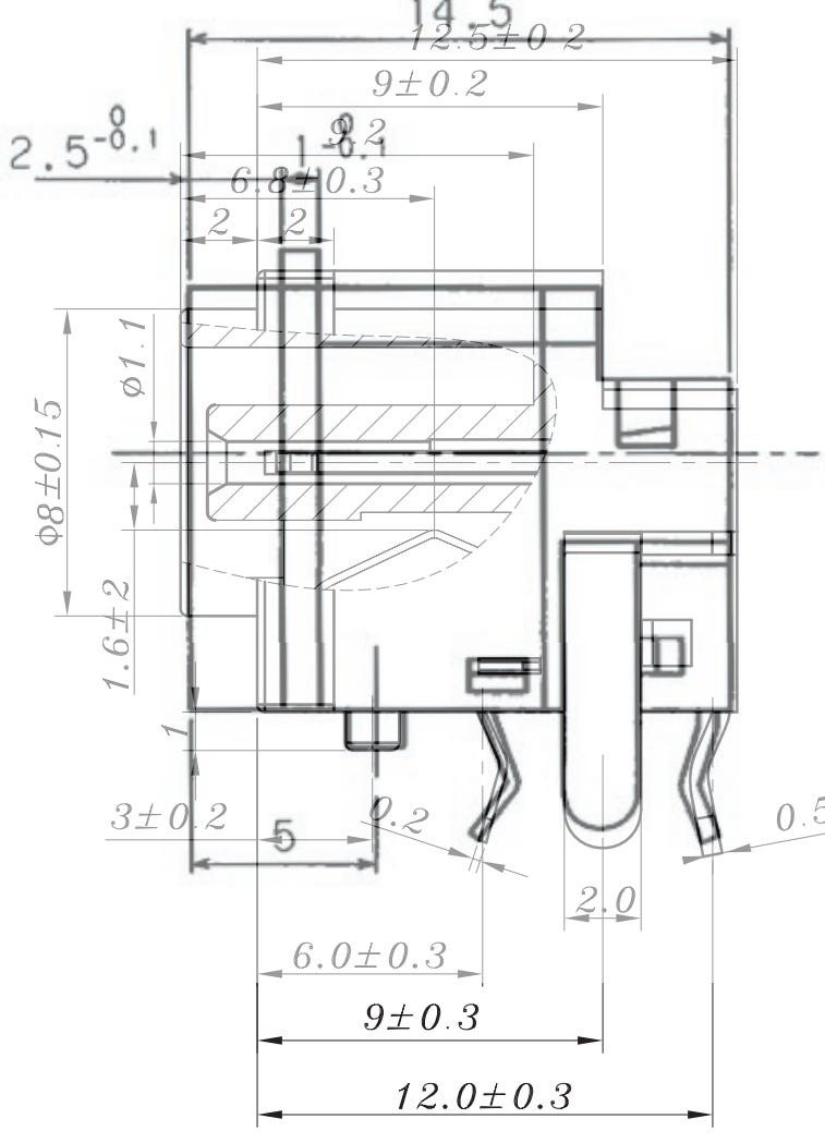
The closest (appears to be a direct clone actually) I was able to find is the Lumberg 1613 19, though it’s listed on Farnell as no longer manufactured. We do have a datasheet though, and the drawing dimensions and footprint match what’s on the board pretty much perfectly:
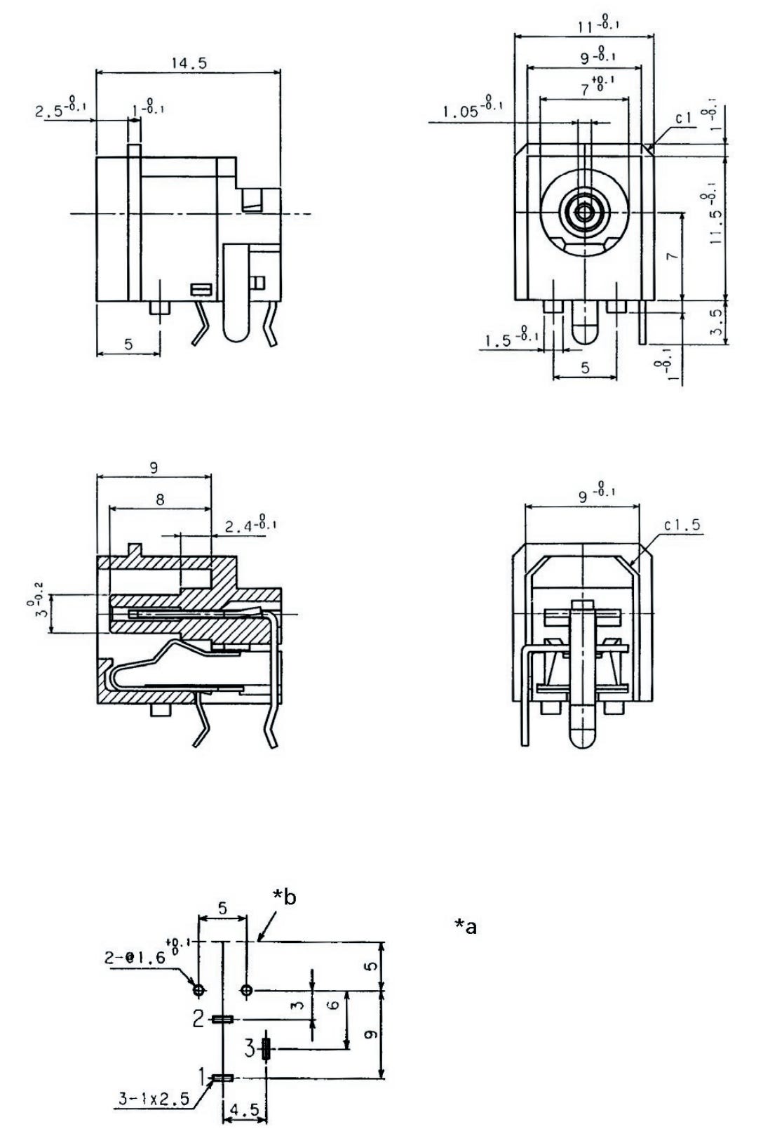
I was able to use this drawing however to identify a few alternates.
The footprint is almost a perfect match (see overlay with Lumberg footprint below), varying only in:
4.3mm vs 4.5mm pitch from Pin 1/2 to Pin 3
0.8mm vs 1mm slot diameter
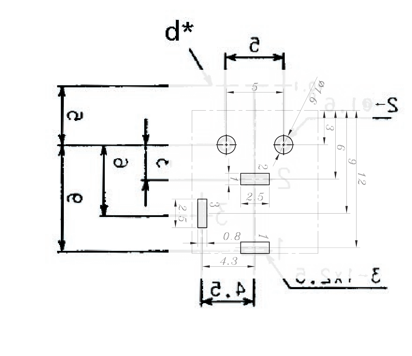
You can disregard the difference in the guide post-to-board edge dimension (3mm vs 5mm), as this is is not the mating face of the connector. Overlaying the side views, we can see that the critical dimensions (mating face to pins) are the same:
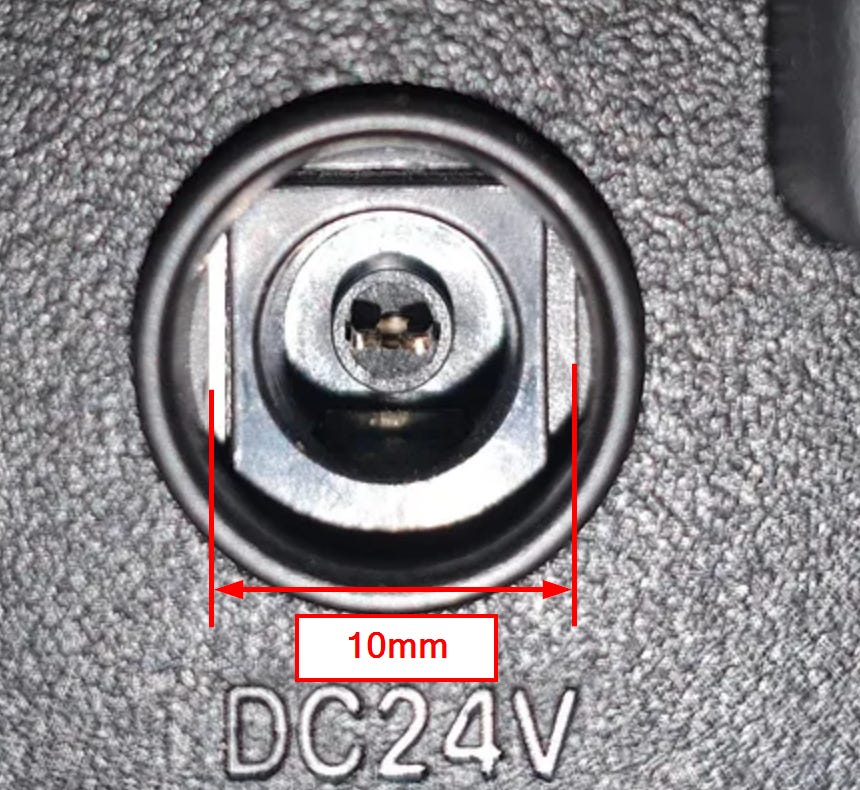
The PJ-019 will poke through the panel cut out in housing slightly, however this shouldn’t be a problem as the squared-off width of the cut out measures 10mm, while the shroud OD is 8.15mm max.
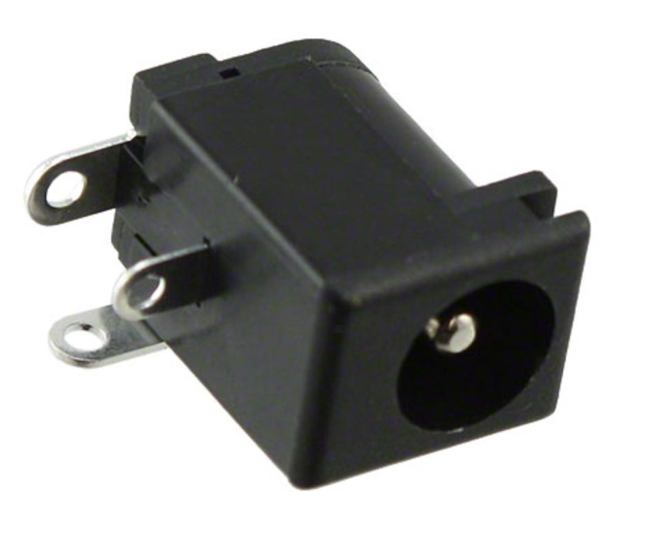
This one is virtually identical to the PJ-019. Even better, the recommended footprint matches the Lumberg one exactly.
I can’t really see any significant difference between this and the LDC-058-2 honestly. I’ve alt-tabbed between the two drawings and can’t spot any meaningful differences. The only difference that I can see, is the Insertion Depth parameter on the product pages, which is listed as 9.00mm for the LDC-058-2 and 9.50mm for the LDC-123.
Feel free to comment any other alternates you come across below.
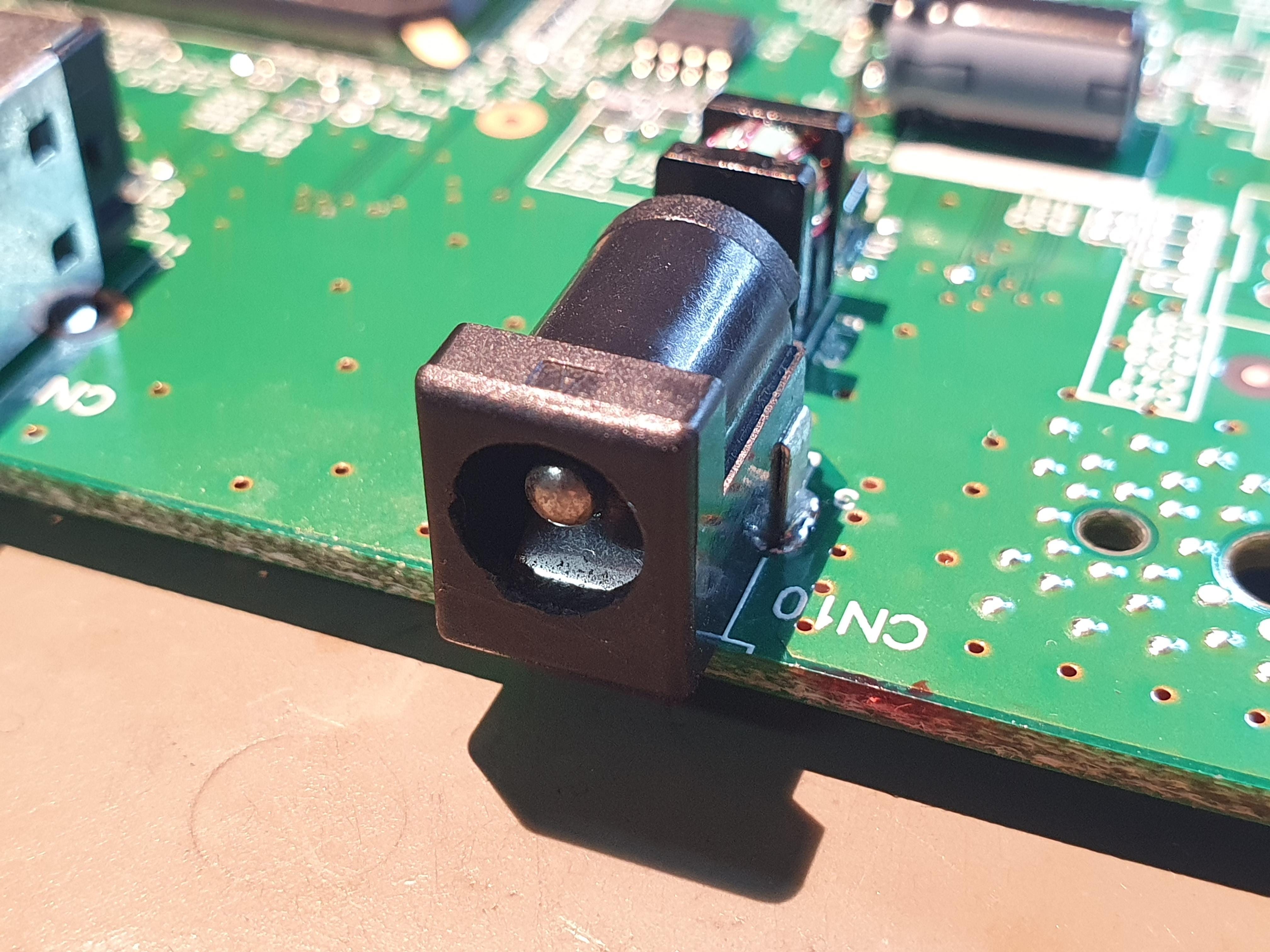
As for this repair, since the original power supply is long gone, I will be replacing this connector entirely with a much more ubiquitous barrel jack. I just so happened to have a 24V, 1.5A centre positive power brick in my spares with a 5.5mm OD, 2.1mm ID plug. If you’d like to do a similar mod to your unit, a jack like the Same Sky PJ-002AH is well stocked on Digikey/Mouser and should drop in to the same footprint nicely.
Upon plugging in the replacement power supply, the unit came to life. Though there was a new problem. I could see the cross carriage (both top and bottom), as well as the lens assembly moving/homing at start-up. However after the light bars did their start-up flash routine, the LED above the power button would transition to flashing red. Looking at the troubleshooting page on Epson’s website, they provide some possible causes:
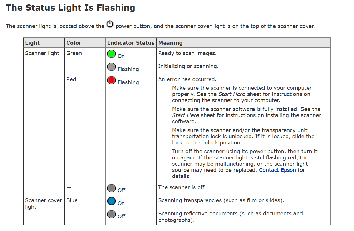
The first is to make sure the scanner is connected to a PC. Plugging it in, the unit enumerates and can be seen by Windows Fax and Scan. Upon trying to scan/preview, the same thing happens. Lens/cross carriage assemblies home, light bars flash, and the power indicator starts blinking red.
Next it says make sure the scanner software is installed. Obviously this isn’t the issue, otherwise the built-in Windows scan software wouldn’t see the device.
It suggests checking the transport locks. Obviously these are unlocked otherwise we wouldn’t be able to see the cross carriages (both top and bottom) moving, and there would be sounds of belts grinding/protesting.
Finally it suggest that if a power cycle doesn’t fix what ails it, then it’s “malfunctioning, or the scanner light source may need to be replaced.”
Not overly helpful, but the reference to the light source needing replacement is curiously specific. Though I doubt there’s this much intelligence designed into some LED bar drivers for a scanner, it’s possible that they’re monitoring the current through each LED strip to validate that they’re in expected range. Potentially there’s a dead LED in one of the strips that’s affecting the overall measurement.
I took the diffuser covers off the two LED bars and filmed the start-up sequence in slow-motion. This allowed me to check each LED. Unsurprisingly, both strips were fine. I also tested with the top half of the scanner entirely removed (connects to the bottom with a single mini-DIN cable). but the result was the same - red flashing LED after carriage homing.
Here’s what the problem turned out to be: the cover frame with the glass pane wasn’t installed. Make no mistake, there are no smarts (magnets, switches or otherwise) used to detect whether this cover is installed. However what it does have is a reflective strip at the edge of the glass used for calibration during the power-on self-test and homing routine. With the cover off, it naturally fails this calibration as it does not see the reflective strip and reports a non-descript error. In my attempt to be thorough and check that everything was working before buttoning the unit up, I was sent on a wild goose chase.
I’ve attached a video below of what a successful start-up sequence should look like, for anyone trying to troubleshoot their own unit.
0:02 - 0:05: Lens assembly homing
0:05 - 0:08: Top and bottom cross carriage assembly homing
0:08 - 0:11: LED backlight and CCD verification (will fail here if the cover is off)
Take note of what the video sounds like and compare it to your own unit. If you hear belt grinding noises during lens assembly homing, you either have a damaged or disengaged belt, or the optical trip wire sensor (opto-interrupter) isn’t triggering to indicate end of travel. The optical sensor won’t trip if the plastic shutter (part of the lens carriage) is broken, the sensor is damaged, or its cable harness is damaged or unplugged.
If either of the cross carriages don’t move, assuming you’ve already checked both transport locks, check the belts. If there’s no sound at all, check the wiring to the stepper motors.
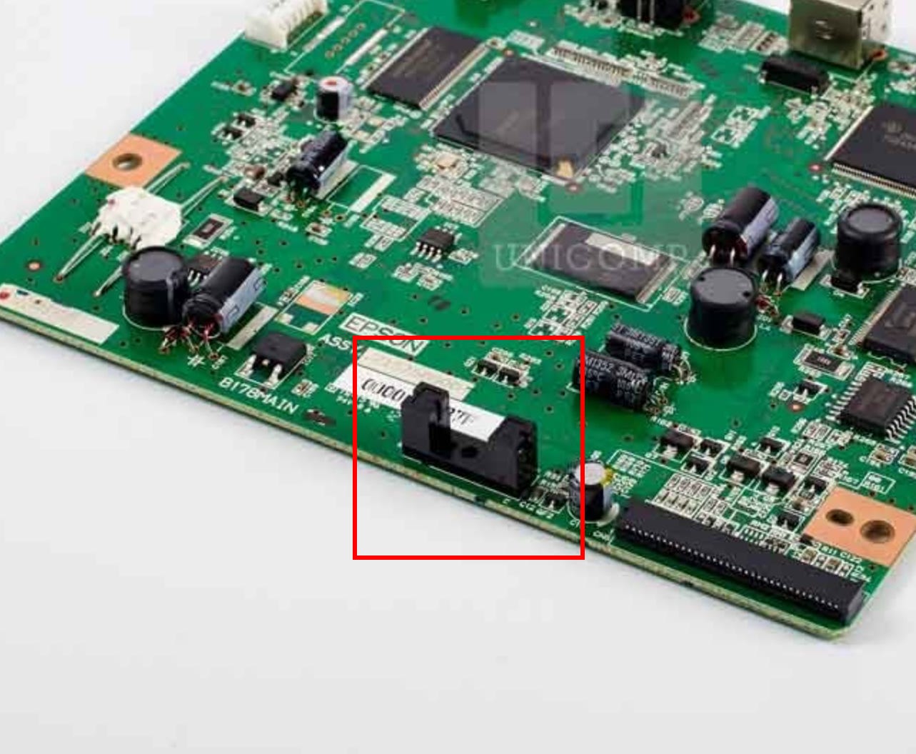
If the cross carriages move, but there’s a belt grinding noise at the end of their travel, the optical sensor is likely not being triggered. Check that the opto-interrupter isn’t physically damaged (see below for the one on the main board), and check that the plastic shutter underneath the cross carriage isn’t broken (it looks like a shark fin).
The LED bars are a little trickier to check, as only one of them is visible for most of the start-up sequence (second becomes visible on the last homing movement). These are pretty simple boards though; each has 20 LEDs (or 25 can’t remember exactly) in 4S5P (or 5S5P) configuration. If you have dark spots in the light bar, this indicates one or more of the LEDs in a series chain has failed short. The dark spots will be large (20 or 25% of the length missing) if the LED has failed open. If the whole bar is failing to illuminate, check the FFC cable is seated in the LIF connector and not torn.
If everything looks and sounds intact mechanically, LED bars are turning on, and you’re still getting a red flashing light, assuming you’re not testing the unit partially disassembled like I was, this likely indicates an issue with the CCD board. I’m not sure if Epson will supply or repair the CCD board out of warranty, but worth reaching out to them.
That’s it for now.
No posts
Comments
Nothing yet. Say the first thing.
Sign in to join the conversation.