
Article 6 ended on a frustration. The Nyquist and Bode methods we spent five articles building are powerful, but they carry an awkward burden: to assess whether a converter is stable, you need to know the grid it is connected to. And because the impedance is a linearisation, you need to repeat the assessment at every operating point, for every credible grid condition. Change the grid, add a neighbour, shift the loading, and the study must be redone.
For a single connection this is merely laborious. For a modern grid — hundreds of converters, each seeing a network that shifts hour by hour as other plants switch in and out — it becomes close to impossible. Every converter’s stability depends on every other converter and on a grid impedance that no one knows exactly and that never stops changing.
What if there were a way out? A property a converter could carry that guarantees it will never destabilise the grid — any grid — no matter the operating point, no matter what else is connected, checkable on the converter alone without knowing anything about the network?
There is. It is called passivity, and it is the most elegant idea in the whole field.
Passivity is not new. It is one of the oldest and deepest ideas in electrical engineering, and its power comes from a simple physical fact. A passive component — a resistor, a capacitor, an inductor, any interconnection of them — is one that can only consume, store, or return energy. It has no internal source. It cannot generate energy, and therefore it cannot, on its own, generate or sustain an oscillation.
This is the whole intuition for why passivity guarantees stability. An oscillation that grows over time is an oscillation being fed energy. If every element in a circuit is passive — if none of them can supply net energy — then there is nothing to feed a growing oscillation, and the system must be stable. Connect any number of passive components together, in any arrangement, and the result is still passive, still stable. Passivity is preserved under interconnection. That is the property that makes it so useful.
For an impedance, passivity has a precise and beautifully simple mathematical form. An impedance is passive if the real part of its complex value is greater than or equal to zero at every frequency. The real part of an impedance is its resistive component — the part that dissipates energy. When the real part is positive, the device absorbs energy at that frequency, like a resistor. When the real part is negative, the device supplies energy at that frequency — it behaves, in that narrow band, like a source rather than a sink. And a source can feed an oscillation.
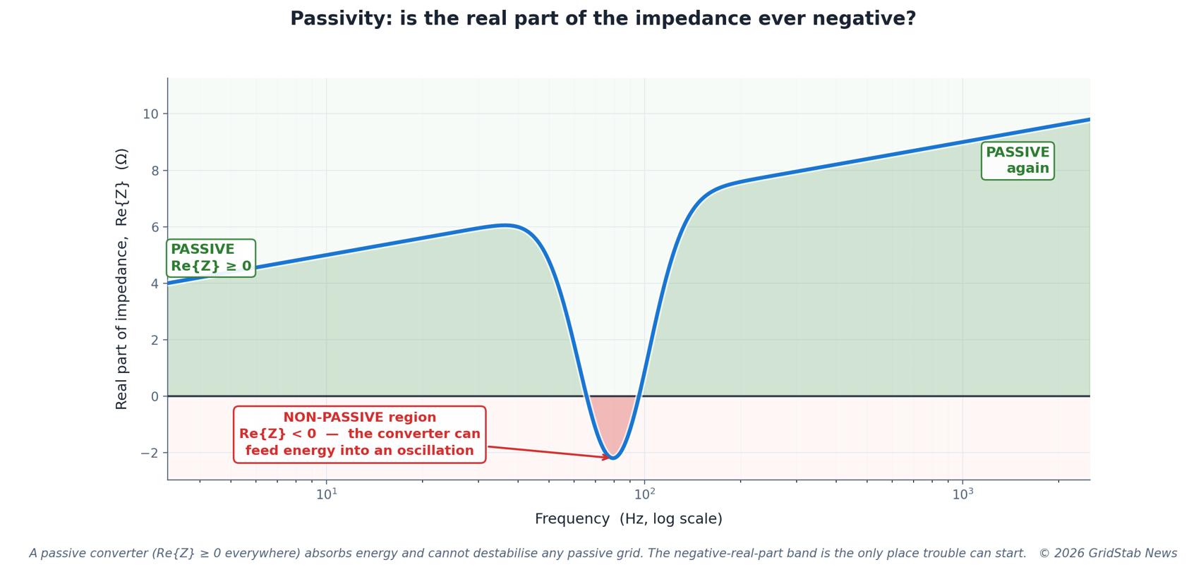
Figure 1. Passivity is a question about one quantity: the real part of the converter’s impedance. Where Re{Z} ≥ 0 (green) the converter absorbs energy and is passive. Where Re{Z} < 0 (red) it can supply energy to an oscillation — the only region where instability can begin. A converter that is passive at every frequency cannot destabilise any passive grid.
Figure 1 shows what this looks like in practice. The curve is the real part of a converter’s impedance across frequency. For most of the range it sits comfortably above zero — passive, safe. But in one band it dips below zero. That negative-real-part region is the entire game. It is the only place where the converter can act as an energy source, and therefore the only place where an interaction with a grid resonance could grow into an instability. Everywhere else, the converter is guaranteed harmless.
—— YOU ARE ~30% INTO THIS ARTICLE ——
What follows behind the paywall
● The superpower: local check, global guarantee (with diagram) — why passivity lets you certify each converter alone and skip the system-wide study entirely.
● The price of the shortcut — passivity is sufficient but not necessary, and therefore conservative. What that costs, and why it can be worth paying.
● The realistic compromise — why nothing real (not even a synchronous generator) is passive everywhere, and the frequency-threshold split that shares responsibility between converter maker and grid operator.
● Passivity in the grid codes — where it is already written into real requirements (GB Grid Code GC0137, AEMO, ENTSO-E, EN 50388-2) and where it is heading.
● How converters are made passive — the control-design levers that shrink the negative-real-part region, and the synthesis with everything in this series.
Subscribe to GridStab News to unlock the full article and the rest of the series.
NEXT IN THE SERIES — ARTICLE 8
Putting it all together: how the whole impedance-based toolkit fits, when to use which tool, and what it means for designing and connecting converters on a converter-dominated grid.
The final article of the series — free to all readers. Subscribe so you don’t miss it.
Comments
Nothing yet. Say the first thing.
Sign in to join the conversation.