HP MJF 3D Printing Service
HP Multi Jet Fusion (MJF) is a powerful 3D printing technology that produces highly accurate and durable parts at fast speeds, especially compared to other powder bed fusion technologies like selective laser sintering (SLS) or direct metal laser sintering (DMLS). Due to their affordability, speed, and high resolution, multi jet fusion technology can be used for end-use, low-volume production, rapid prototyping, or as a bridge process to injection molding. MJF allows engineers to get a feel for how parts will perform with minimal upfront costs.
Upload your 3D CAD file to get instant pricing and lead times for a variety of materials. If needed, you can easily select a different process or material to receive an updated quote in real time. Xometry offers free shipping on all 3D printing orders originating in the US.
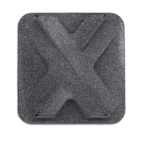
MJF Printing Materials
HP MJF Materials Available at Xometry:
| Material Name | Use Case Examples | Shore Hardness | Elongation at Break (XY, ZX %) | Impact Strength (XY, ZX kJ/m²) | Data Sheet |
|---|---|---|---|---|---|
Material Name Nylon 11 | Use Case Examples Snap fits, clips, living hinges | Shore Hardness 80D | Elongation at Break (XY, ZX %) 55%, 40% | Impact Strength (XY, ZX kJ/m²) 6 kJ/m², 5 kJ/m² | Data Sheet |
Material Name Nylon 12 | Use Case Examples General-purpose functional parts | Shore Hardness 80D | Elongation at Break (XY, ZX %) 20%, 15% | Impact Strength (XY, ZX kJ/m²) 3.6 kJ/m², 3.5 kJ/m² | Data Sheet |
Material Name Nylon 12, White | Use Case Examples General-purpose white parts; dyeable | Shore Hardness N/A | Elongation at Break (XY, ZX %) 17%, 9% | Impact Strength (XY, ZX kJ/m²) 4.5 kJ/m², 4.4 kJ/m² | Data Sheet |
Material Name Nylon 12, Smooth | Use Case Examples Aesthetically demanding rigid parts | Shore Hardness N/A | Elongation at Break (XY, ZX %) 12%, 5% | Impact Strength (XY, ZX kJ/m²) 2.5 kJ/m², 2.0 kJ/m² | Data Sheet |
Material Name Nylon 12, Multi-Color (CB) | Use Case Examples Full-color realistic prototypes | Shore Hardness N/A | Elongation at Break (XY, ZX %) 20%, 14% | Impact Strength (XY, ZX kJ/m²) 3.1 kJ/m², 2.8 kJ/m² | Data Sheet |
Material Name Nylon 12, Glass-Filled | Use Case Examples Enclosures, housings, fixtures, and tooling | Shore Hardness 82D | Elongation at Break (XY, ZX %) 10% | Impact Strength (XY, ZX kJ/m²) 3 kJ/m² | Data Sheet |
Material Name Polypropylene (PP) | Use Case Examples Chemical-resistant fluid containers | Shore Hardness N/A | Elongation at Break (XY, ZX %) 20% | Impact Strength (XY, ZX kJ/m²) 3.5 kJ/m², 3.0 kJ/m² | Data Sheet |
Material Name TPU 88A | Use Case Examples Sports equipment, footwear, grippers | Shore Hardness 88A | Elongation at Break (XY, ZX %) 280%, 150% | Impact Strength (XY, ZX kJ/m²) No break | Data Sheet |
Material Name TPU 88A (M88A) | Use Case Examples Flexible, skin-safe wearables | Shore Hardness 88A | Elongation at Break (XY, ZX %) 440%, 125% | Impact Strength (XY, ZX kJ/m²) N/A | Data Sheet |
Properties apply to US-based production. Not all options are available for Xometry's international economy option.
Performance Finishes
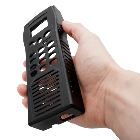
Vapor Smoothing
Xometry can vapor smooth 3D printed parts to achieve an exceptional surface finish. Vapor smoothing, performed through AMT PostPro3D's technology, is a batch-based automated smoothing process that achieves a high-quality sealed surface with a semi-gloss appearance. Our color-dyed finishes can also be combined with vapor smoothing for additional customization options.
Cerakote
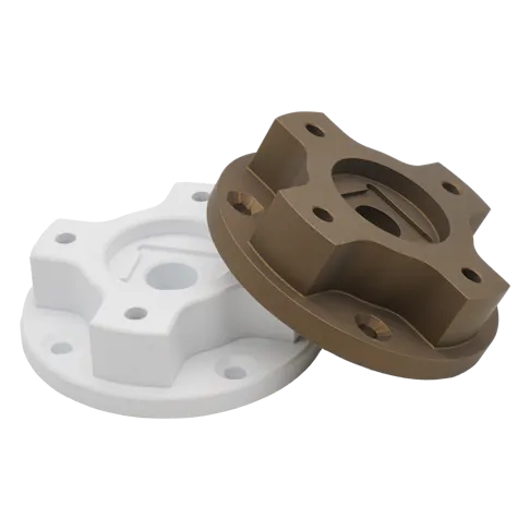
Cerakote is a polymer-ceramic composite coating engineered to improve physical performance properties such as abrasion, wear, corrosion, and chemical resistance, as well as overall surface hardness. The coating is applied by spraying it onto a part and curing it. The typical application thickness of both the C-Series and H-Series formulas is 0.5 to 1.0 mils (0.0005" to 0.001").
Resources from HP
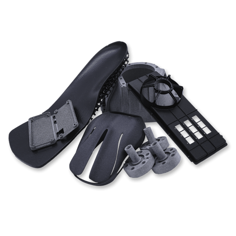
HP 3D Printing Materials Guide
HP MJF Mechanical Properties Whitepaper
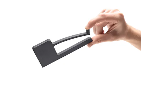
The aim of this white paper is to illustrate the achievable mechanical properties of HP 3D Printing materials.
HP MJF Dimensional Accuracy Whitepaper
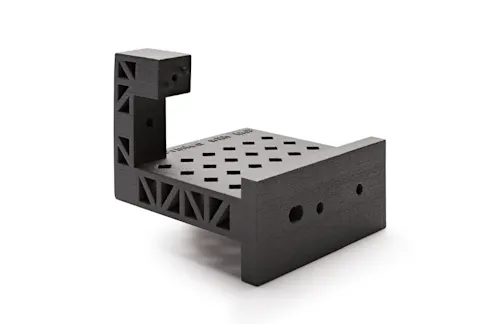
The aim of this whitepaper is to provide information on the dimensional capabilities that can be achieved with HP MJF.
HP MJF Handbook
Applications for HP MJF
Concept Models
The speed and versatility of MJF let product developers create tough and detailed physical snapshots of their designs.

Rapid Prototyping
MJF can be used to create fully-functional prototypes, complete with moving parts, as well as all-in-one assemblies.

Direct Digital Manufacturing
The low price and speed of Multi Jet Fusion make it an ideal way to build large quantities of discrete or customized parts.
HP MJF Prototyping Tolerances
In the table below, you will find our standard MJF tolerances for prototype orders. These include one-off or first-time prints, non-production orders, and auto-quoted orders that have not received a manual engineering review.
MJF Prototype Tolerances Based on HP 5200-Series, Balanced Mode
| Material Type | Under 30 mm (1.2") | 30 - 50 mm (1.2" - 2.0") | 50 - 80 mm (2.0" - 3.2") | > 80 mm (3.2") |
|---|---|---|---|---|
Material Type Rigid Materials (Nylon, PP) | Under 30 mm (1.2") ± 0.70 mm (.028") | 30 - 50 mm (1.2" - 2.0") ± 0.85 mm (.033") | 50 - 80 mm (2.0" - 3.2") ± 1.40 mm (.055") | > 80 mm (3.2") ± 1.75 % |
Material Type Rubber-Like (TPU) | Under 30 mm (1.2") ± 1.05 mm (.041") | 30 - 50 mm (1.2" - 2.0") ± 1.35 mm (.053") | 50 - 80 mm (2.0" - 3.2") ± 1.80 mm (.071") | > 80 mm (3.2") ± 2.25 % |
Results are typical for MJF orders without additional engineering review.
HP MJF Engineer Reviewed & Production Tolerances
Tolerances tighter than prototype tolerancing can be guaranteed after additional engineering review. This includes higher volume production part orders and orders manually optimized by our engineering teams, often after an initial prototyping run.
Engineered & Production MJF Tolerances Based on HP 5200-Series, Balanced Mode
| Material Type | Under 30 mm (1.2") | 30 - 50 mm (1.2" - 2.0") | 50 - 80 mm (2.0" - 3.2") | > 80 mm (3.2") |
|---|---|---|---|---|
Material Type Rigid Materials (Nylon, PP) | Under 30 mm (1.2") XY = ± 0.25 mm (.010") | 30 - 50 mm (1.2" - 2.0") XY = ± 0.30 mm (.012") | 50 - 80 mm (2.0" - 3.2") XY = ± 0.39 mm (.015") | > 80 mm (3.2") XY = ± 0.5 % |
Material Type Rubber-Like (TPU) | Under 30 mm (1.2") XY = ± 0.60 mm (.024") | 30 - 50 mm (1.2" - 2.0") XY = ± 0.60 mm (.024") | 50 - 80 mm (2.0" - 3.2") XY = ± 0.60 mm (.024") | > 80 mm (3.2") XY = ± 0.75 % |
Results are typical for orders which have gone through manual engineering review and initial prototyping runs.
HP MJF Feature and Build Size
| Description | Tolerance Notes |
|---|---|
Description Manufacturing Standards | Tolerance Notes |
Description Build Area | Tolerance Notes Build area up to 15 x 11 x 15" (14 x 11 x 13" is the recommended usable area). |
Description Minimum Feature Size | Tolerance Notes 0.020" (0.040" recommended) or greater. |
Description Layer Thickness | Tolerance Notes 80 Microns (0.0031") |
Description HP Dimensional Accuracy Report | Tolerance Notes |
Stresses during the build and other geometry considerations may cause deviation in tolerances and flatness. Part designs with thicker geometries, flat or broad parts, and parts with uneven wall thicknesses may be prone to significant deviations or warp.
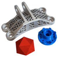
Need to Compare Printing Processes?
Our quick reference guides let you quickly compare different 3D printing processes!
Overview: What is HP Multi Jet Fusion?
The Basics of HP MJF
HP Multi Jet Fusion is a powerful 3D printing technology that produces highly accurate and durable parts that are capable of being used directly in end-use, low-volume production, or for rapid prototyping. Since the process uses well-established 2D printing ink-jetting, it has remarkably fast layer times compared to other powder bed fusion technologies.
How Multi Jet Fusion 3D Printing Works
Like all powder-based 3D printing processes, multi jet fusion technology builds parts layer by layer, using a fusing agent and heat to set each layer before moving onto the next. In the more traditional processes — such as Selective Laser Sintering (SLS), Stereolithography(SLA), or Direct Metal Laser Sintering (DMLS)— each part is imaged, layer by layer, with a single laser beam. HP’s Multi Jet Fusion works a bit more like a traditional ink-jet printer with a printhead that deposits the material, and then a fusing agent, across the entire build plate in one pass, allowing for the printing of multiple parts simultaneously.
The Benefits of HP’s Multi Jet Fusion 3D Printing Process
While there are many benefits to HP jet fusion, a few truly stand out. For starters, the standard build parameters are optimized for best density. The result is that Multi Jet Fusion parts are watertight.
If you like SLS but want to produce higher quantities for small-batch production runs, Multi Jet Fusion is the way to go. The ability to print multiple parts simultaneously across the entire build volume means you can print parts at rates up to 10X faster than SLS or other 3D printing processes. Also, Multi Jet Fusion delivers more balanced mechanical properties across the X, Y, and Z axes than SLS.
If you’re interested in injection molding for your project, it’s always a good idea to get a 3D printed “test” part before making the investment in metal molds. While SLA is a great 3D printing process for extremely detailed and high-resolution prints, the UV-cured resins are not as tough as traditional thermoplastics. Prints begin to degrade when exposed to UV light and moisture.
On the other hand, Multi Jet Fusion can produce accurate prints while also maintaining the structural durability of traditional thermoplastics, especially when using glass-filled nylon. This makes it an excellent process for testing fit and functionality before taking your project to injection molding.
Why Choose Xometry for HP MJF?

Endless Options
Choose from millions of possible combinations of materials, finishes, tolerances, markings, and certifications for your order.

Easy to Use
Get your parts delivered right to your door without the hassle of sourcing, project management, logistics, or shipping.

High Quality
We are ISO 9001:2015, ISO 13485, IATF 16949:2016, and AS9100D certified.
