I'll preface this with the fact that I'm using my own board that I designed, so I don't expect that much support. I've just gotten to the point where I'm fully stumped on the issue so I figured I'd give you as much info as I have to see if you have any ideas since you've been involved in this much longer than I.
Display is a used Kindle ED060SC4, VCOM is set to same voltage as barcode sticker, -1.3V, using esp-idf with an ESP32-WROVER.
I have 2 issues:
- The full right side of my display doesn't really work and I can't change it intentionally. This is a non-issue for this post, only mentioning to acknowledge the pics
- I can correctly address the display to draw along the X axis. However, whatever X coordinate I draw is always copied for the entire vertical column
The more times I draw to an X-coordinate, the darker that vertical line gets. For example:
int x_coord = 0;
uint8_t color = 0;     // pretty sure this is black right?
uint8_t line_length = 50;
for (int x = x_coord; x < 300; x += 50) {
    for (int y = 0; y < line_length; i++) {
        epd_draw_pixel(x_coord, y, color, fb);
    }
}
I would expect this to result in 6 vertical black lines 50 pixels down from the top. What actually appears is 6 very faint lines from top to bottom of the display. Any line_length below 50 is basically invisible on the display.
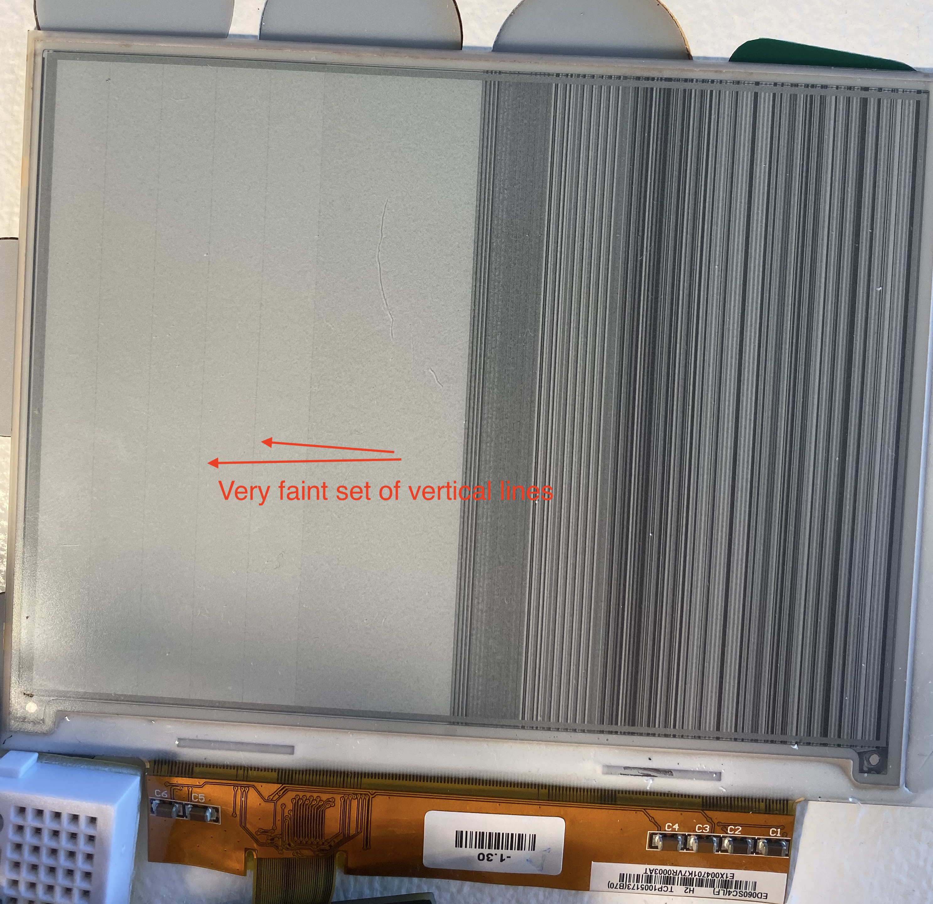
Instead of drawing 50 pixels, let's bump it to 200
...
uint8_t line_length = 200;
... (rest of code identical)
This then makes a much darker line instead of the expected 200 pixel tall line.
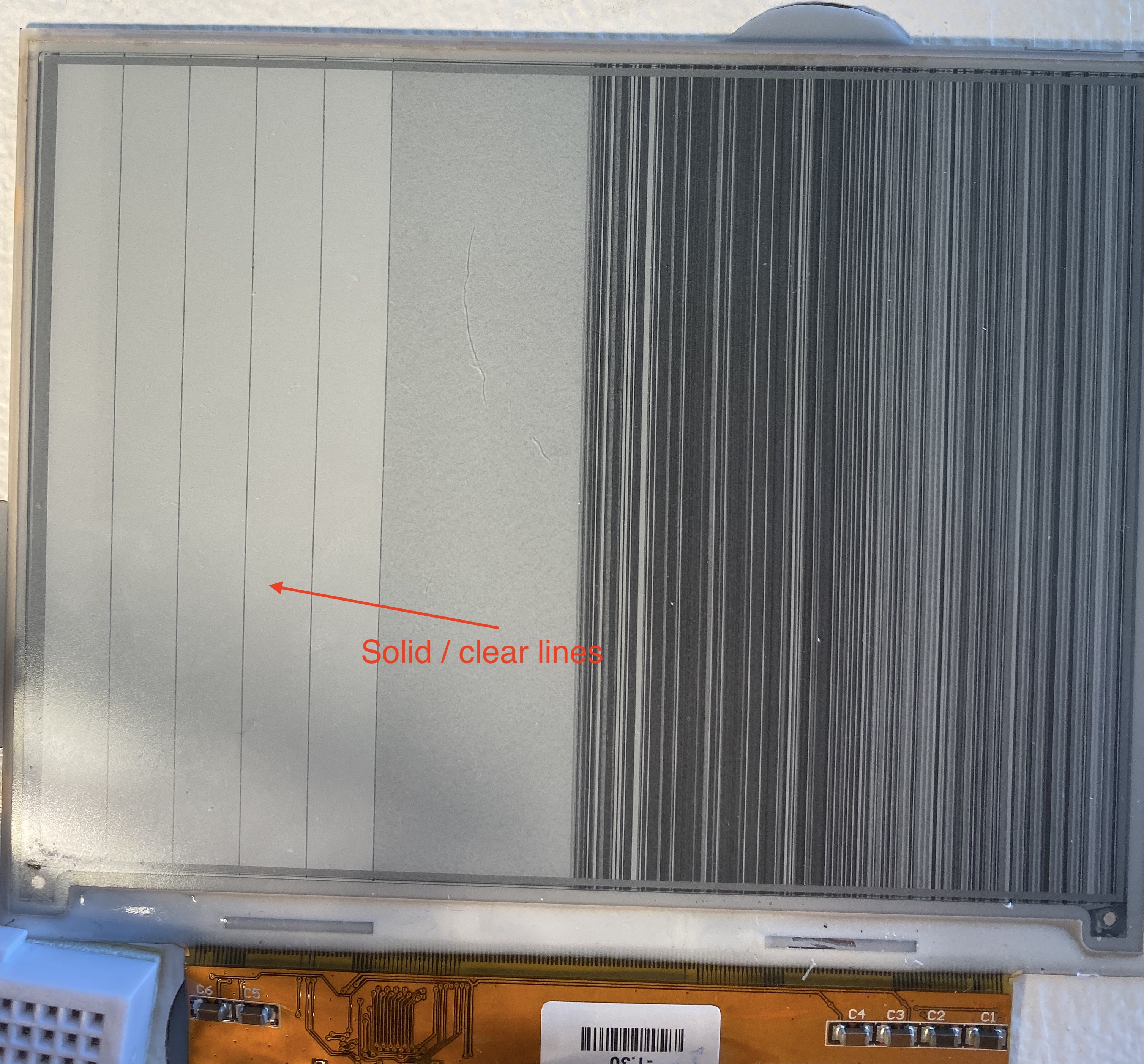
Minimal repro code in this repo: https://github.com/dot4qu/ed060sc4-breakout-driver
My theory is that no matter where on the Y axis the firmware is attempting to draw, it's getting clocked to every single Y coordinate at that X point. Attempting to draw anything horizontal where I keep the X coordinate constant and vary the Y coordinate shows nothing on the display.
I've gone deep into the weeds with a logic analyzer on every control signal comparing to the explanation on essentialscrap and everything seems to line up pretty well. There are some weird-ish differences from epdiy (i.e. some wiggling of GMODE before it goes fully high) but the fact that I can correctly clear and draw kind of as expected tells me the overall driving signals are good.
The one part I'm most suspicious of is the logic to latch and advance each row's data, but the LE/OE signals seems to be just fine. The other alternative is that something is weird with the data the ESP is outputting and it's just sending the same values on the DATA lines every row instead of just for the expected row. I captured D0-D7 on my saleae as well but those are weird waveforms and I don't know how to read them.
I've attached the two saleae files if you have the Logic app and wouldn't mind taking a brief look to make sure everything looks okay. It's a free download (~120MB) if you don't but I also totally understand you not wanted to deal with that so I can screenshot different sections/zoom levels if that will help debug.
Appreciate any insight you can give - happy to throw a few bucks your way for your time as well if you have a GitHub sponsor thing or similar.