Subject
Add LEGO style CSI annotation formatting
Environment
Version of LPub3D - 2.3.7
Operating system - All
Solution
Assembly Globals Setup - Display, Annotation settings
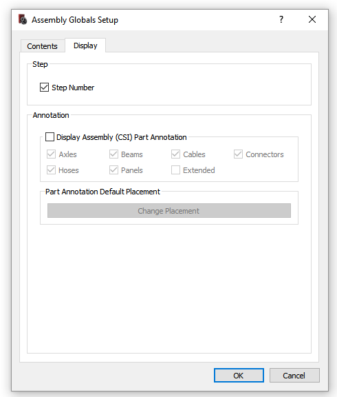
Display Assembly (CSI) Part Annotation - enable or disable Fixed (Axles, Beams, Cables, Connectors, Hoses, or Panels) or Extended (Title, Free Form, or both) annotation display. Title and Free Form annotations uses the Extended style. The remaining styles are used by Fixed annotations. All annotation styles use one of three shape configurations - square, circle, or rectangle. Extended annotation styles use the Rectangle shape configuration. Axle and Panels use the Circle shape configuration and Beams, Cables, Connections, and Hoses uses the Square shape configuration
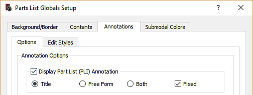
NOTE Assembly (CSI) part annotation display is ultimately controlled by the global PLI part display settings at Part List Globals Setup, Annotations, Options, Display Part List (PLI) Annotation
Part Annotation Default Placement - set the default annotation placement which can also be changed from the annotation context menu.
See #186 for additional details on part annotation configuration and setup.
The following steps present nominal assembly (CSI) annotation setup and execution flows:
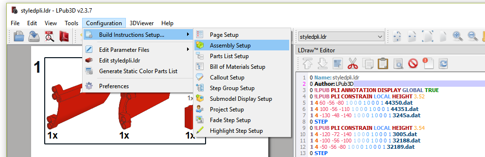
Menu item
Default settings
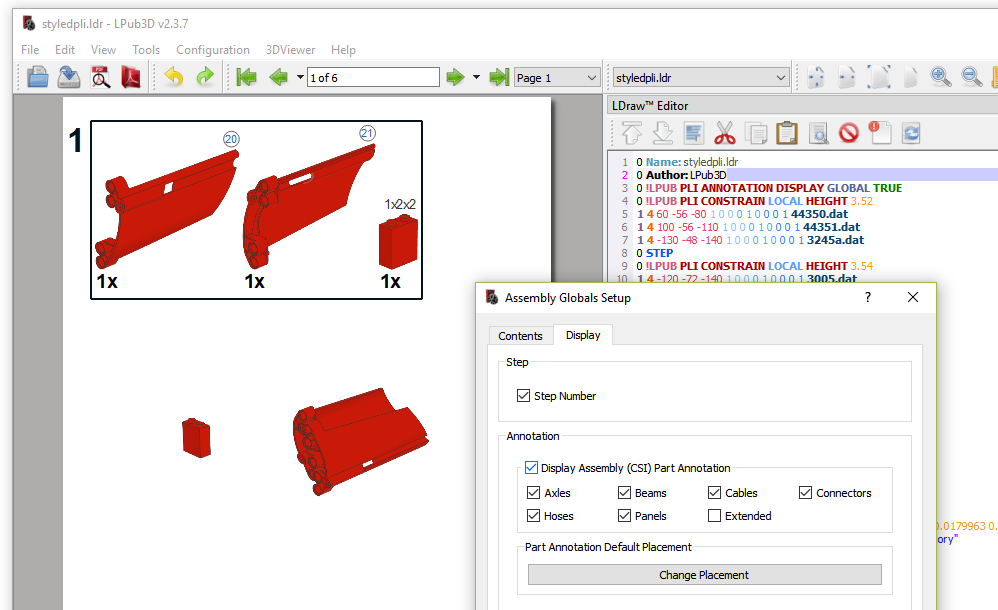
Assembly part annotations
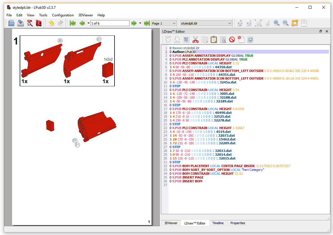
NOTE - CSI annotation position information is calculated and persisted to the model file using the CSI image dimensions. Once written, further model file loads will not automatically update the position information. If the image dimensions are subsequently updated, or the renderer is changed, the CSI annotation position may fall out of alignment with its respective part image.
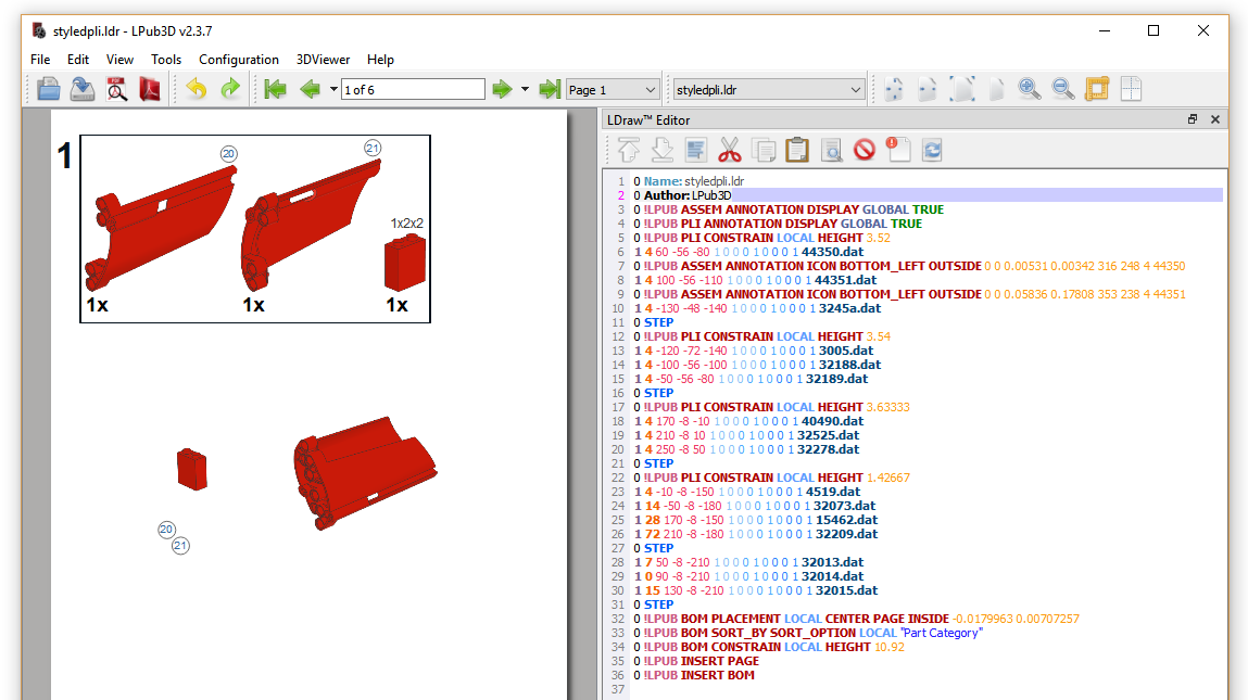
The next steps illustrate this behaviour and the actions required to reload and realign the CSI part annotation (CSI part annotation position information manually changed to illustrate an out of alignment scenario):
CSI annotation and part image out of alignment.
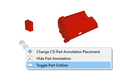
Toggle part outline context menu item
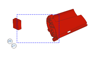
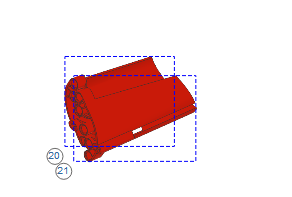
Part outline - - confirm annotation position is out of alignment
Reload Part Annotation context menu item - accessed from CSI image context menu
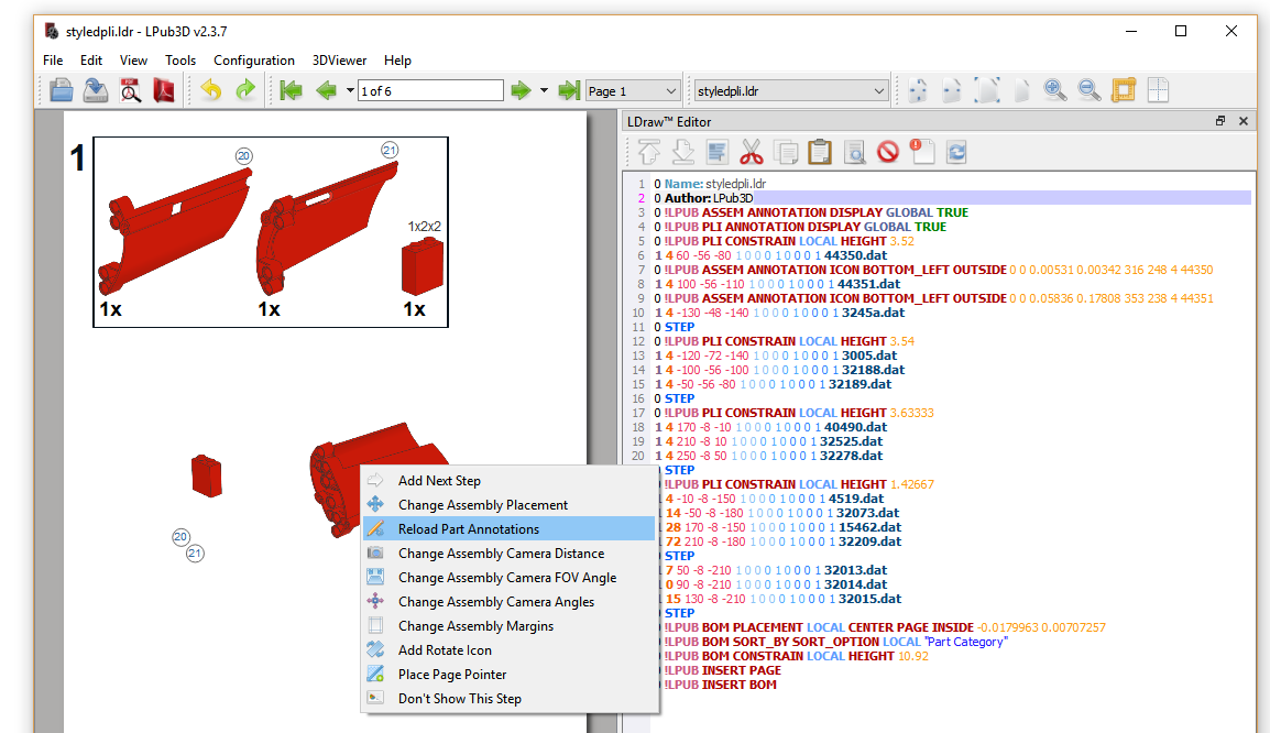
Realigned CSI part annotation
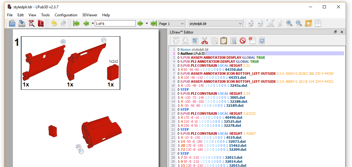
Part outline - confirm CSI part annotation position is well aligned
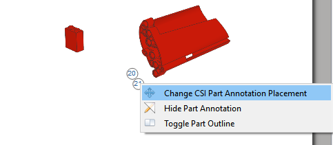
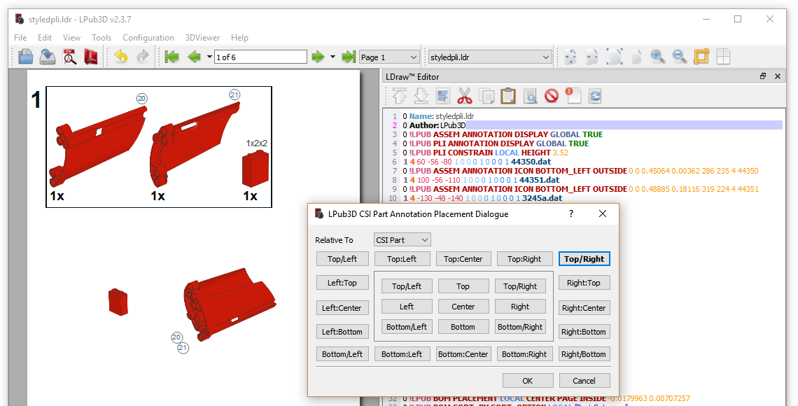
Change CSI Part annotation placement context menu - accessed from CSI part annotation
Placement dialogue - set CSI part annotation placement top/right (from bottom/left)
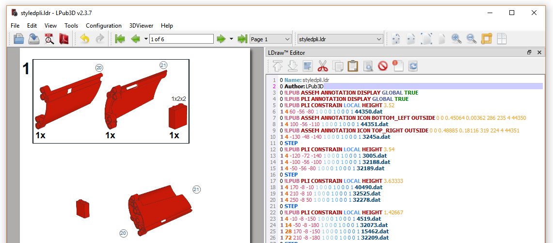
Repositioned CSI part annotation - top/right
NOTE: CSI annotations are also drag enabled so, in addition to using the placement dialogue, one can simply drag the annotation to the desired location.