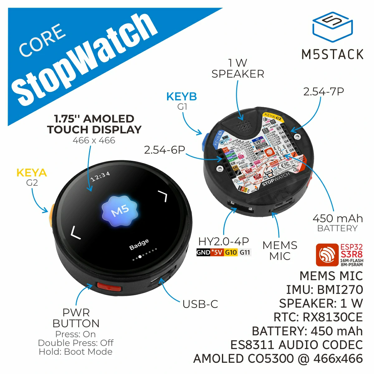
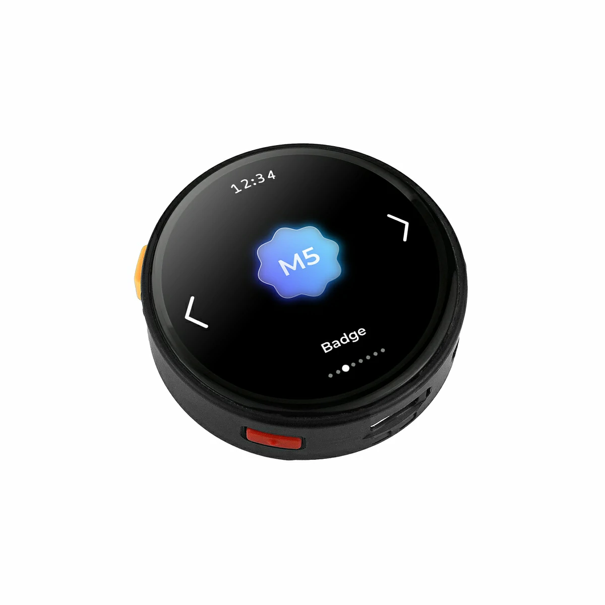
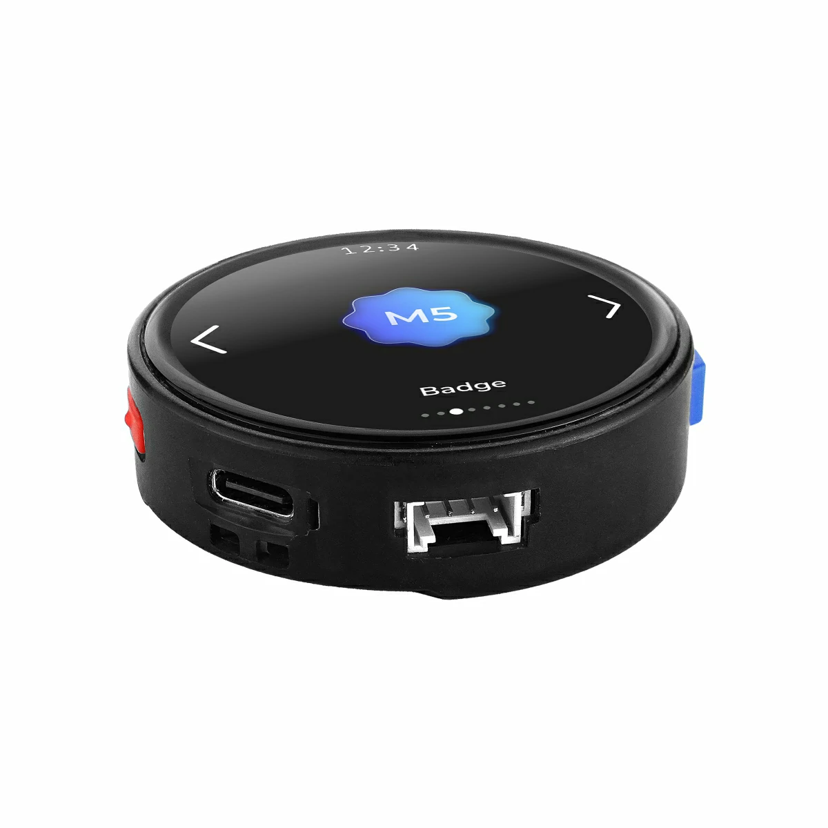
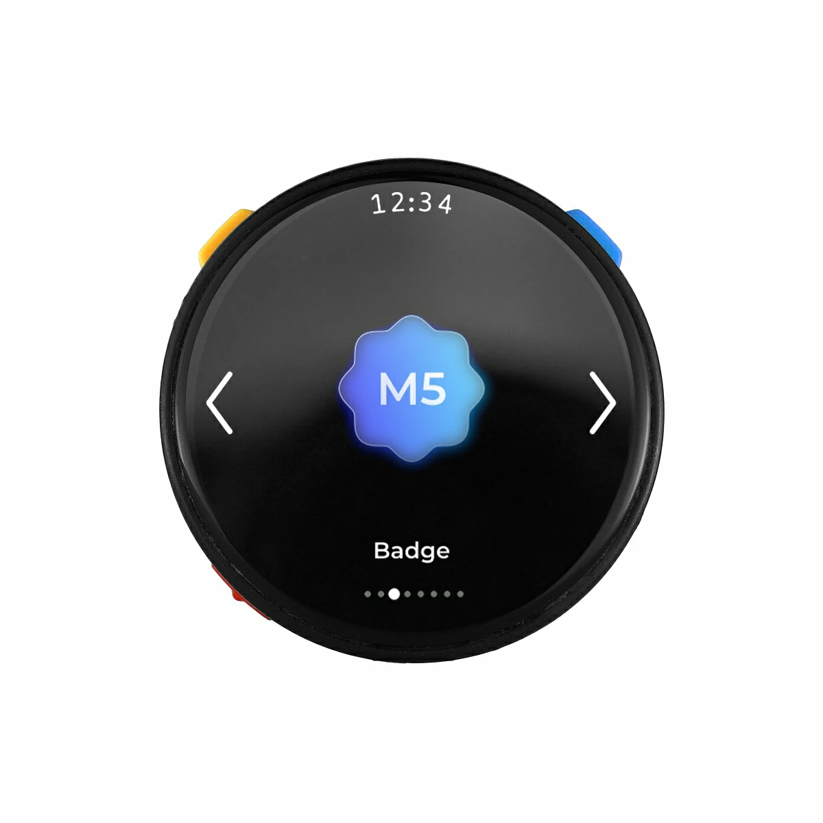
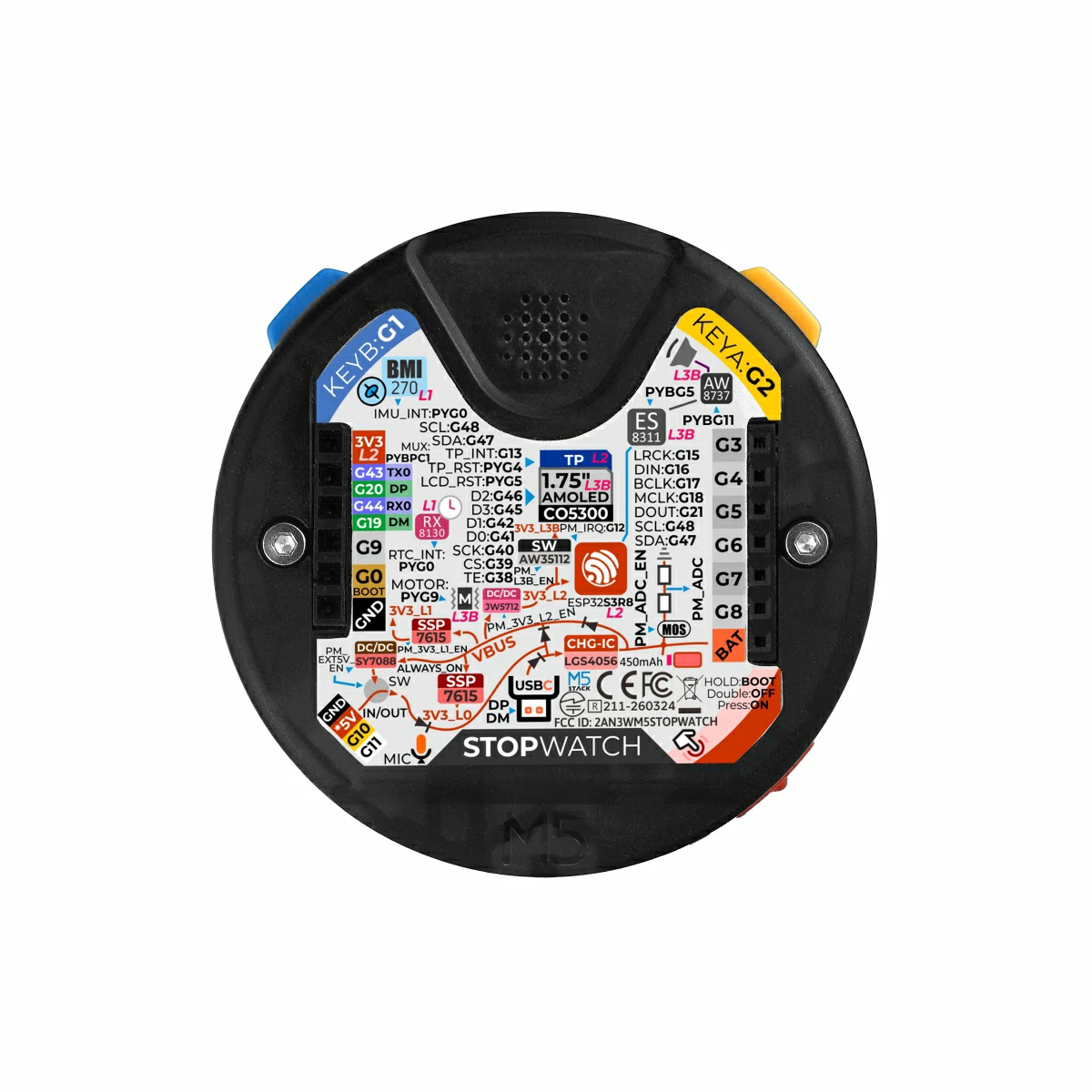
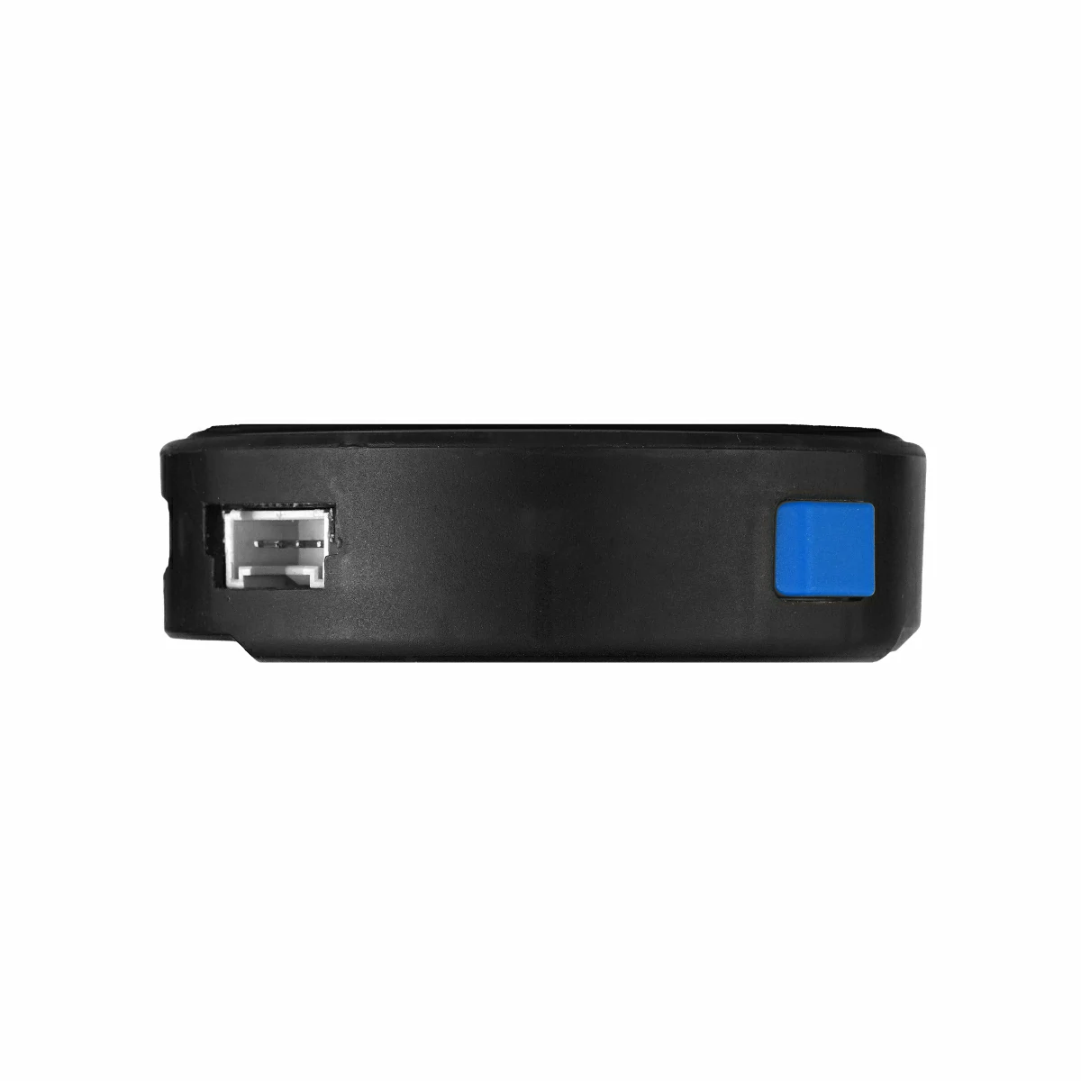
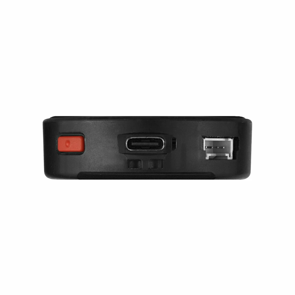
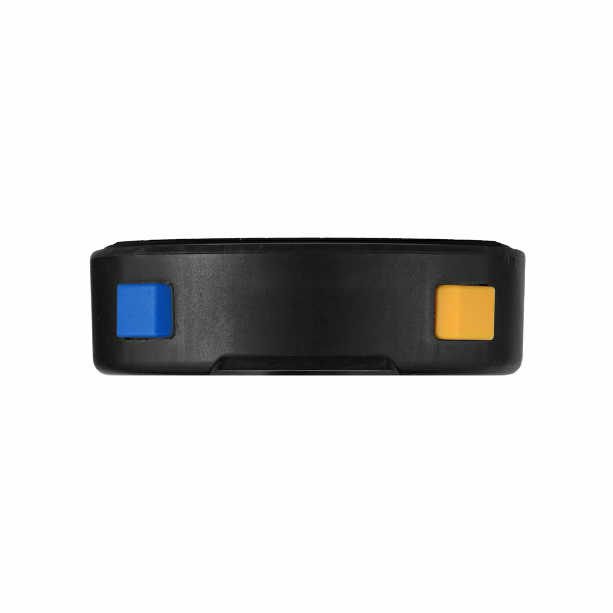
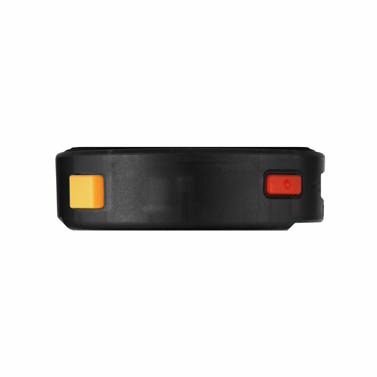
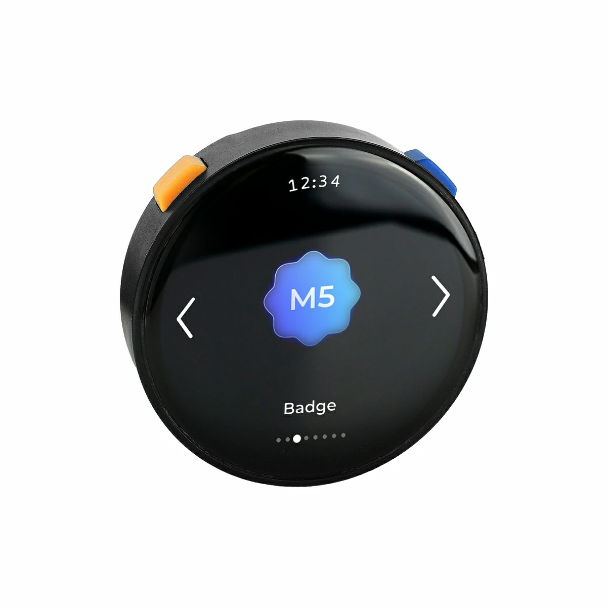
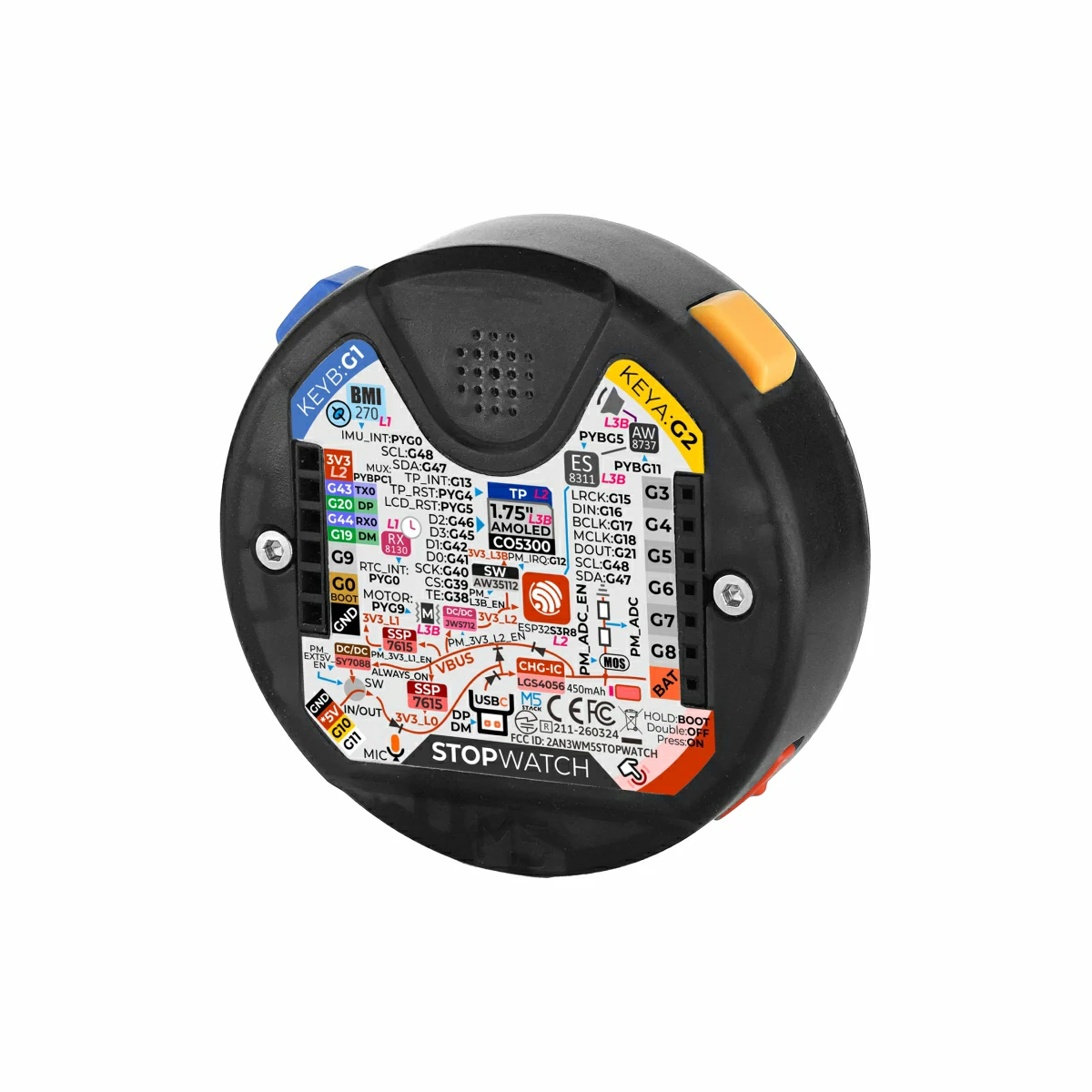
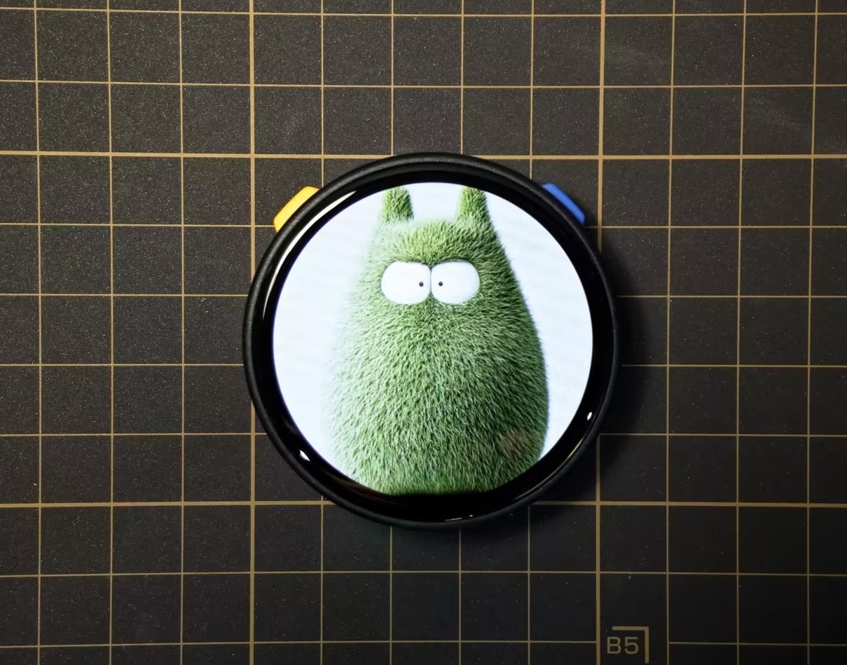
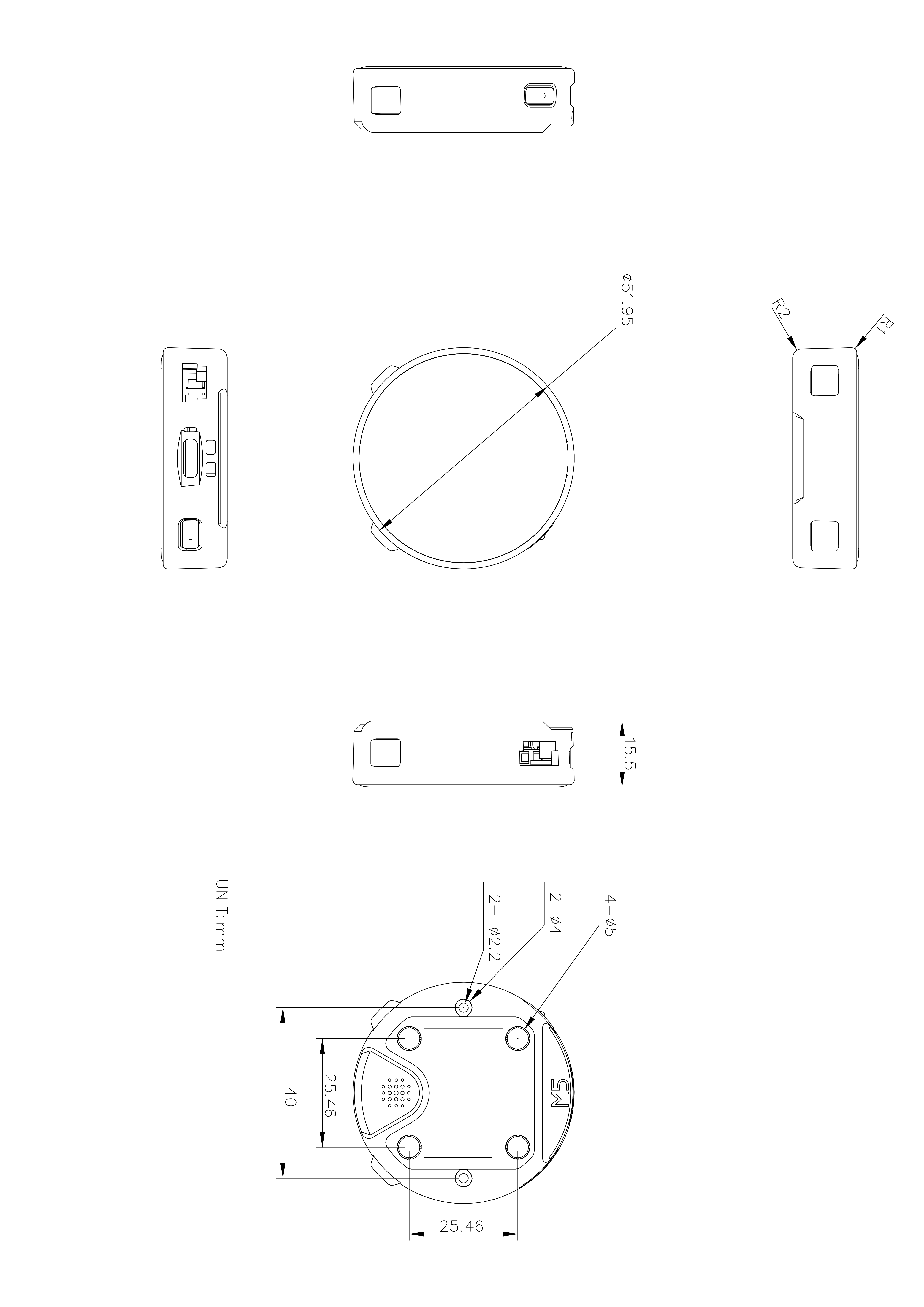
StopWatch is a round AMOLED touch development board designed for portable and interactive scenarios. It features an ESP32-S3R8 main controller with 16MB Flash and 8MB PSRAM, supporting 2.4GHz Wi-Fi wireless communication. The device integrates a 1.75" AMOLED touch round screen, programmable buttons, and vibration feedback for an intuitive human-machine interaction experience. It also features audio input/output, IMU attitude sensing, RTC timekeeping, and multiple expansion interfaces. Combined with the M5PM1 multi-level power management system and a 450mAh battery, it meets diverse development needs including portable smart control, wearable human-machine interaction, and lightweight IoT terminals.
Note
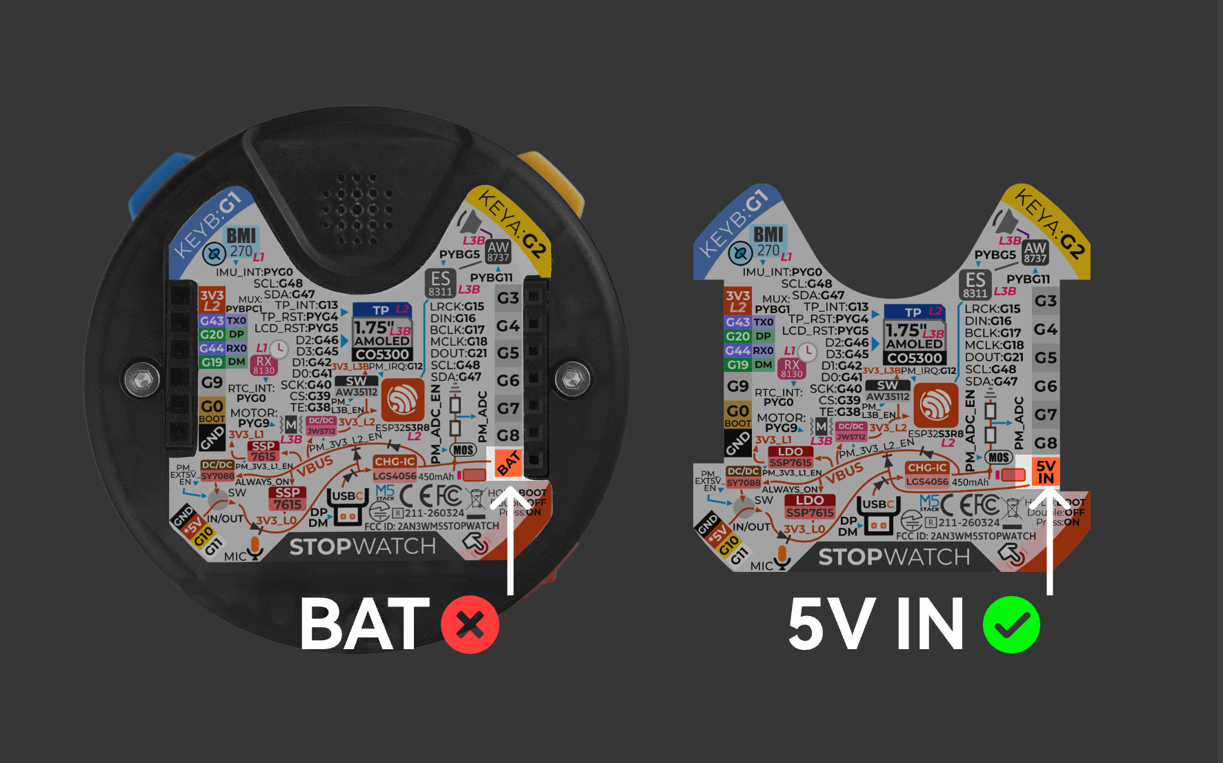
Correction Notice Regarding Label Printing Error
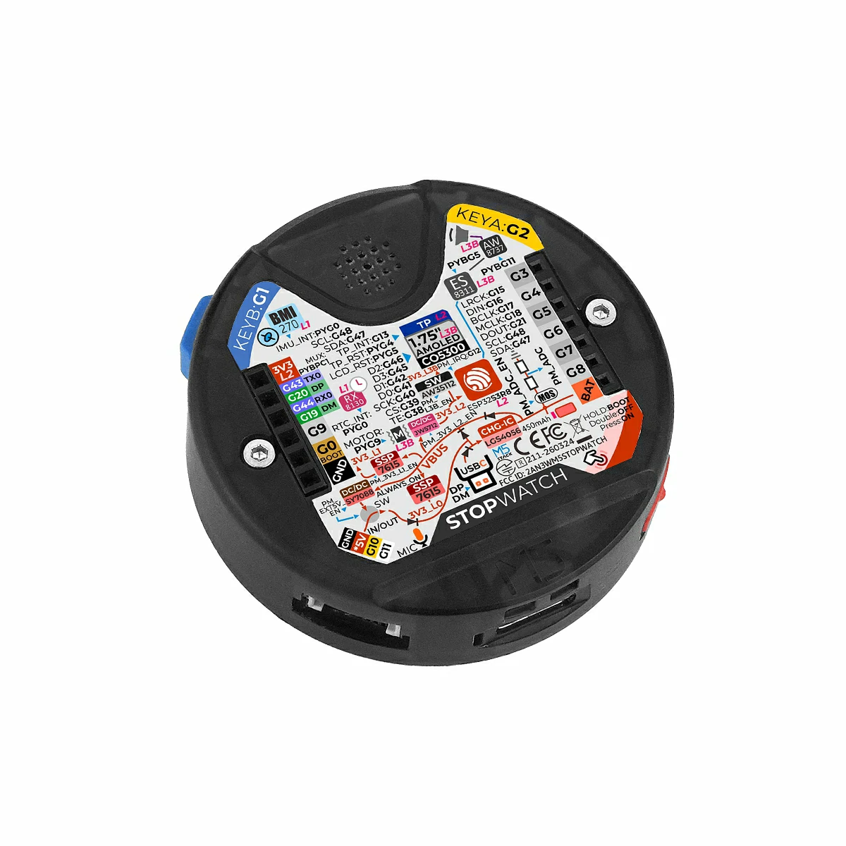
Some product batches have a printing error on the device label: the position indicated by the arrow in the image below is labeled BAT. The actual function of this pin is 5V IN, an input for an external 5V power supply, not a battery pin. Do not connect a lithium battery to it.
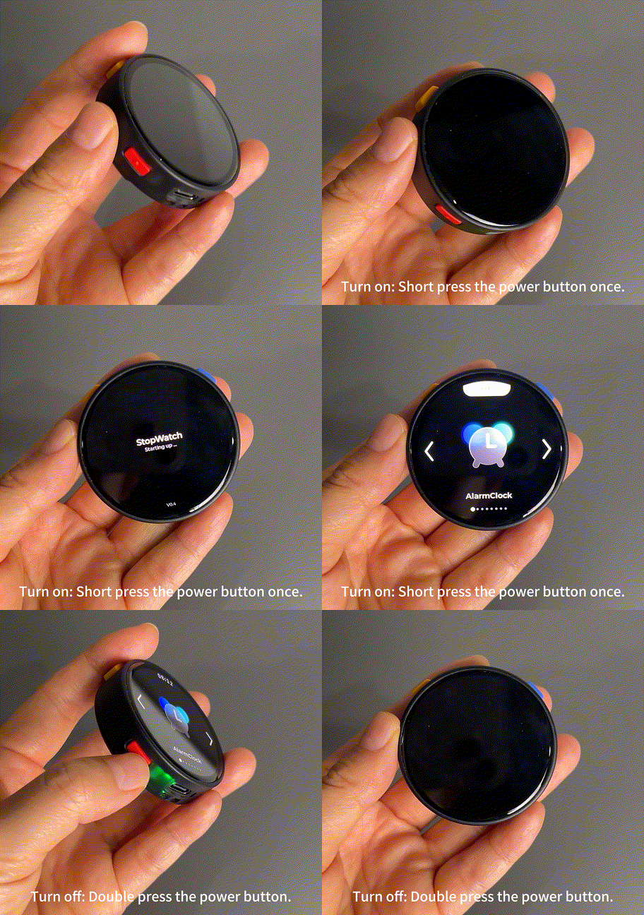
Power On / Reset: Short press the power button once
Power Off: Press the power button twice quickly
Enter Download Mode
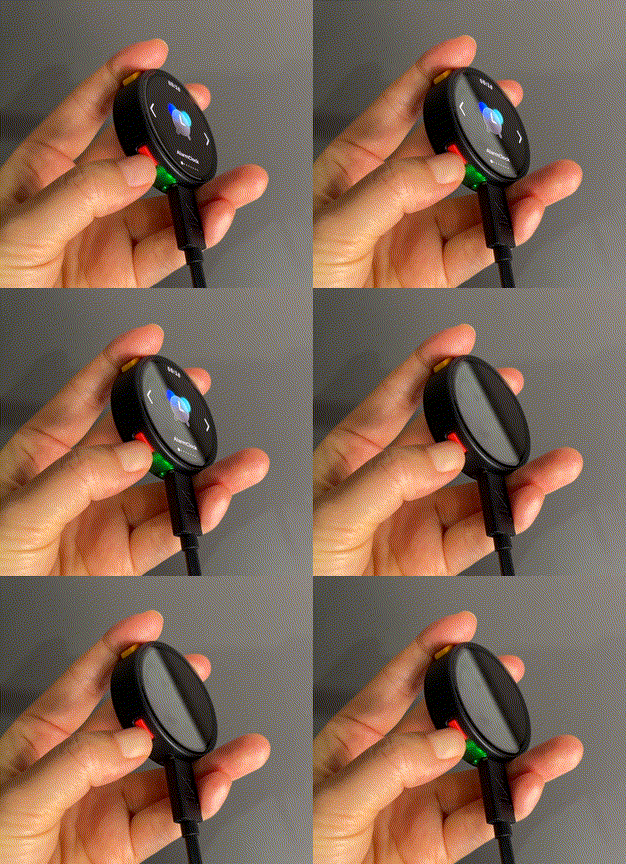
Connect the device to your computer via a USB Type-C cable, press and hold the power button (about 2 seconds) until the green LED lights up, then release. The device is now in download mode, ready for flashing.
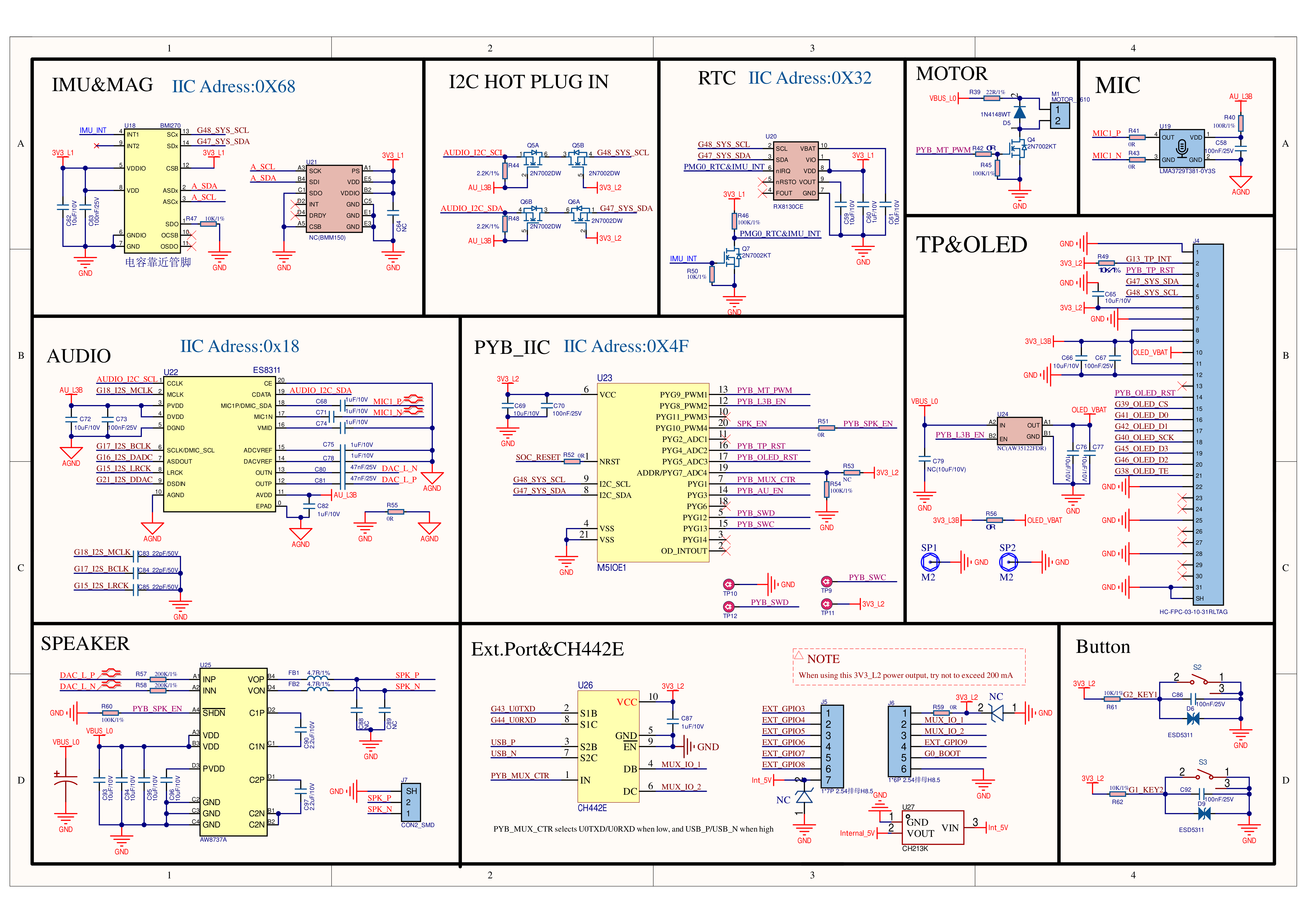
The display reset is controlled via PYG5 (PYB_OLED_RST) of the M5IOE1 expansion chip.
Touch
ESP32S3R8
G47
G48
G13
CST820B
SYS_SDA
SYS_SCL
TP_INT
The touch reset is controlled via PYG4 (PYB_TP_RST) of the M5IOE1 expansion chip.
Audio
ESP32S3R8
G48
G47
ES8311(0x18)
AUDIO_I2C_SCL
AUDIO_I2C_SDA
ESP32S3R8
G18
G17
G16
G15
G21
ES8311
I2S_MCLK
I2S_BCLK
I2S_ASDOUT
I2S_LRCK
I2S_DSDIN
The speaker amplifier (AW8737A) enable is controlled via PYG10(PYB_SPK_EN) of the M5IOE1 expansion chip, and the Audio L3B level power supply for audio peripherals is controlled via PYG3(PYB_AU_EN).
KEY
ESP32S3R8
G2
G1
KEY
KEYA (YELLOW)
KEYB (BLUE)
IMU & RTC
ESP32S3R8
G48
G47
BMI270(0x68)
SYS_SCL
SYS_SDA
RX8130CE(0x32)
SYS_SCL
SYS_SDA
HY2.0-4P
HY2.0-4P
Black
Red
Yellow
White
PORT.A
GND
5V
G10
G11
EXT 2.54 Bus
FUNC
PIN
LEFT
RIGHT
PIN
FUNC
3V3_L2
1
2
G3
G43(UART0_TX) / G20(USB_DP)
MUX_IO_1
3
4
G4
G44(UART0_RX) / G19(USB_DM)
MUX_IO_2
5
6
G5
G9
7
8
G6
BOOT
G0
9
10
G7
GND
11
12
G8
/
13
14
BAT
The MUX_IO_1, MUX_IO_2 pin switching between USB / UART functions is controlled via PYG1(PYB_MUX_CTR) of the M5IOE1 expansion chip. The default function is UART.
PYG1_HAT_SW
EXT MUX_IO_1/2 FUNC
LOW
G43_U0TXD / G44_U0RXD
HIGH
USB_P / USB_N
M5PM1
ESP32S3R8
G48
G47
M5PM1
SYS_SCL
SYS_SDA
M5PM1
DCDC3V3_EN_PP
LDO3V3_EN_PP
BOOST5V_EN_PP
3V3_L2
PM_3V3_L2_EN
3V3_L1
PM_3V3_L1_EN
Grove
PM_EXT_5V_EN
M5PM1
PYG0
PYG2
PYG4
PYG3
PYG1
RTC & IMU
RTC_INT & IMU_INT
CHARGE
CHG_STAT
CHG_PROG
EXT 5VIN
PORT_INT
ESP32S3R8
G12_PY_IRQ
PYG0(RTC_INT & IMU_INT): Interrupt wake-up signal
PYG2(CHG_STAT): Charging status
PMG4(PORT_INT): External power wake-up signal
PYG1(G12_PY_IRQ): Interrupt signal connected to ESP32-S3
PMG3_CHG_PROG: Charging current control
PMG3_CHG_PROG
CHARGE CURRENT
LOW
425mA
HIGH
185mA (Default)
M5IOE1
ESP32S3R8
G48
G47
M5IOE1(0x4F)
SYS_SCL
SYS_SDA
M5IOE1
PYG1
PYG3
PYG9
PYG8
PYG10
PYG4
PYG5
Ext.Port Select
PYB_MUX_CTR
Audio L3B
PYB_AU_EN
Vibration Motor
PYB_MT_PWM
3V3_L3B
PYB_L3B_EN
Speaker AMP AW8737A
PYB_SPK_EN
Touch
PYB_TP_RST
AMOLED
PYB_OLED_RST
PYG1(PYB_MUX_CTR): Rear expansion interface MUX_IO_1/2 switching between USB / UART functions
PYG3(PYB_AU_EN): ES8311 power supply + MIC power supply